KENR6908 5
Troubleshooting Section
Troubleshooting Section
Electronic Troubleshooting
i02547521
System Overview
System Opera
tion
g01277565
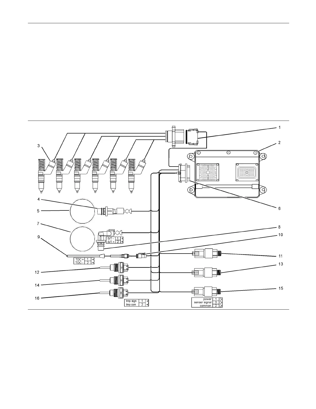
Illustration 1
Block diagram for the 2506-15 engine
(1) 12 Pin Connec tor
(2) Electronic Control M odule (ECM)
(3) E lectronic Unit Injectors
(4) C rankshaft Position Se nsor
(5)36-1ToothGear
(6) 120 Pin Connector
(7)36+1ToothGear
(8) Camshaft Position Sensor
(9) Timing Calibration Probe
(10) Tim ing Calibration Probe Connec tor
(11) Atmospheric Pressure Se nsor
(12) Inlet Manifold Temperature Sensor
(13) Inlet Manifold P ressure Senso r
(14) Coolant Temper ature S ensor
(15) Engine O il P ressure Sensor
(16) Fuel Temperature S ensor
This engine is electronically controlled. Each cylinder
has an electronic unit injector. The Electronic Control
Module (ECM) sends a signal to each injector
solenoid in order to control the operation of the fuel
injection system .
This document has been printed from SPI². Not for Resale