18 KENR6908
Troubleshooting Section
i02835325
Engine Wiring Information
The wiring schematics are revised periodically.
Thewiringsche
matics will change as updates are
made to the machine harness. For the most current
information, always check the revision number of the
schematic. Us
e the schematic with the latest revision
number.
Harness Wire Identification
Perkins iden
tifies all wires with eleven solid colors.
The circuit number is stamped on the wire at a 25 mm
(1 inch) spacing. Table 4 lists the wire colors and the
color codes.
Table 4
Color Codes for the Harness Wire
Color Code Color Color Code Color
BK Black
GN Green
BR Brown BU Blue
RD Red PU Purple
OR Orange GY Gray
YL Yellow WH White
PK Pink
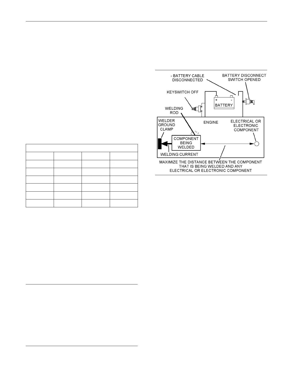
Weldingona
Machine that is Equipped
with an Electronic Control System (ECM)
Proper weld
ing procedures are necessary in o rder
to avoid damage to the engine’s electronic control
module, sensors, and associated components. The
component
that requires welding should be removed.
When welding on a machine that is equipped with an
ECM and removal of the component is not possible,
the follow
ing procedure must be followed. This
procedure provides the minimum amount of risk to
the electronic components.
NOTICE
Do not ground the welder to electrical components
such as the ECM or sensors. Improper grounding can
cause damage to the drive train bearings, hydraulic
components, electrical components, and other com-
ponents.
Clamp the ground cable from the welder to the com-
ponent that will be welded. Place the clamp as close
as possible to the weld. This will help reduce the pos-
sibility of damage.
1. Stop the engine. Turn the keyswitch to the OFF
position.
2. Disconnect the negative battery cable from the
battery. If a b
attery disconnect switch is installed,
open the switch.
g01143634
Illustration 7
Service w elding gu ide (typical diagram )
3. Connect the welding ground cable as close
as possible to the area that will be welded.
Components which may be damaged by welding
include bearings, hydraulic components, and
electrical/electronic components.
4. Protect the wiring harness from welding debris
and from spatter.
5. Weld the materials by using standard welding
methods.
This document has been printed from SPI². Not for Resale