07
For wood stud installation, follow STEP 3A
For concrete installation, follow STEP 3B
Spacers may be necessary for 2 holes ONLY.
Option C (For TV with A “Bump”)
Option D
For cable interference or inset holes,
use spacers [05] to create extra space
between the TV and the faceplate.
D1/E2/F2/F3
06
D1/E1/F1
B
C1/C2
06
04
05
(If needed)
D1/E2/F2/F3
B
C1/C2/C3
06
04
05
(If needed)
Alternate
Spacer
Setups
C1/C2/C3
05
B
04
(If needed)
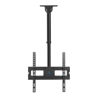
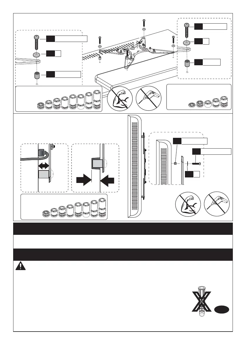
Step 3 Attach the Arm Assembly/Wall Plate [01B] to Wall
Step 3A Wood Stud Option
Wall
Anchor
A2
X
WARNING:
Ensure the arm assembly/wall plate [01B] is securely fastened to
the wall before continuing to the next step.
● Any material covering the wall must not exceed 5/8 in. (16 mm)
● Nominal wood stud size: common 2 x 4 in. (51 x 102 mm) minimum
1.5 x 3.5 in. (38 x 89 mm)
● Stud center must be verified
Avoid potential personal injury or property damage! DO NOT over-tighten the lag
screws [A1]. Tighten the lag screws [A1] only until they are pulled firmly against
the arm assembly/wall plate [01B].
DO NOT USE ANCHOR FOR THIS STEP
Alternate
Spacer
Setups
Alternate
Spacer
Setups