15
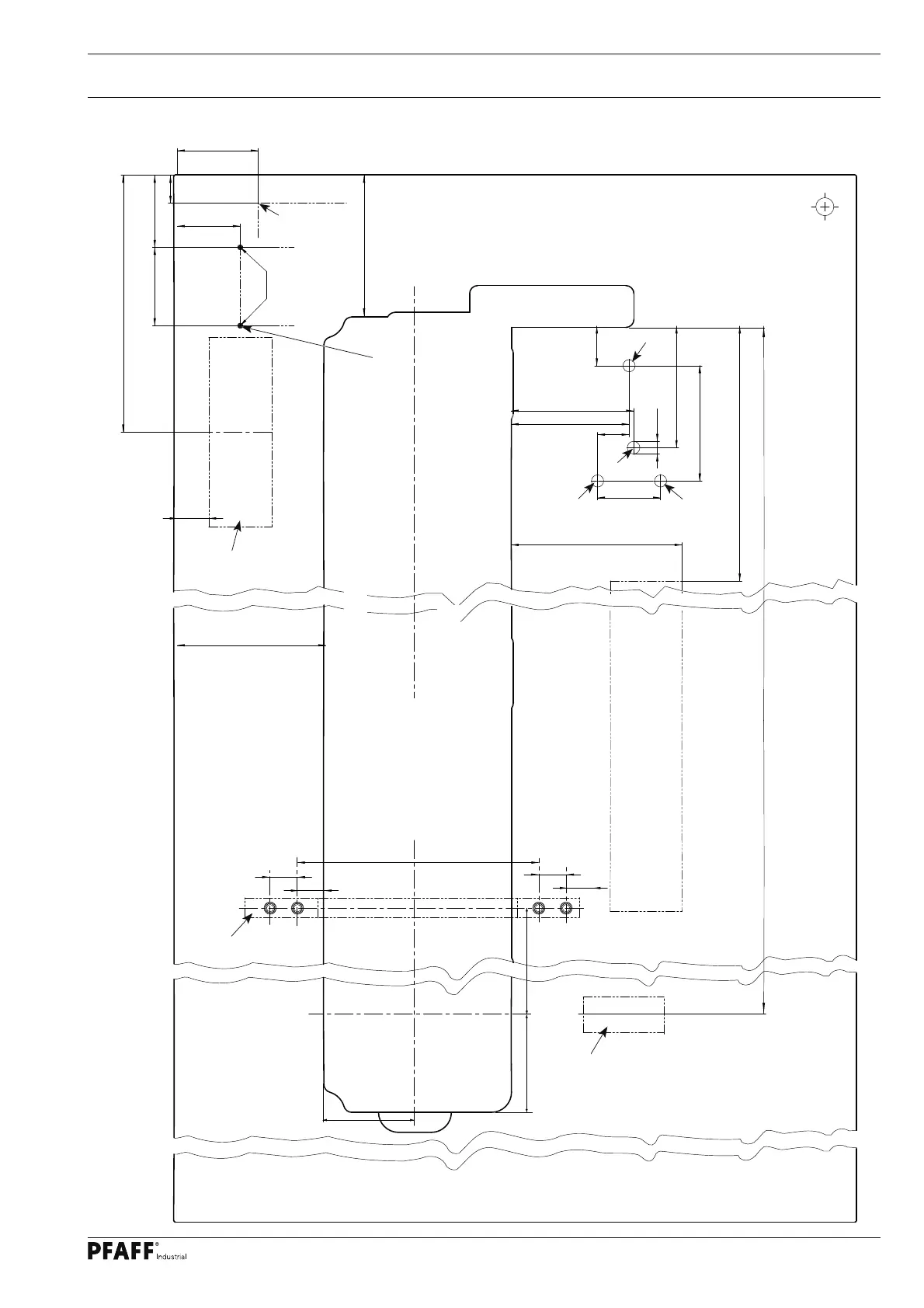
3.02.03 On machines with 1000 mm clearance width
8087
70
31
90
1162
35
285
283
190
70
±0,5
35
131
44
128
±0,3
135
136
165
128
±0,3
156
Ø14
0/1
NM
106
115
535
30
30
30
±0,2
30
±0,2
265
±0,2
Stand position
= Drillholes for fastening the motor
(Screwed inserts M8 x 30 )
= Hole for the sewing head support
= Holes for main switch (P45 PD + P74 ED)
= Braeket for drawer
= Drillholes for fastening the support angle
(Screwed inserts M8 x 30 )
Support angle
91-502 559-71/895
Stand and table top
Controlbox P45 / P74
Speedcontrolunit
P45 / P74
View:
Underside table top
 Loading...