19
Sewing machine drive
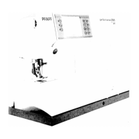
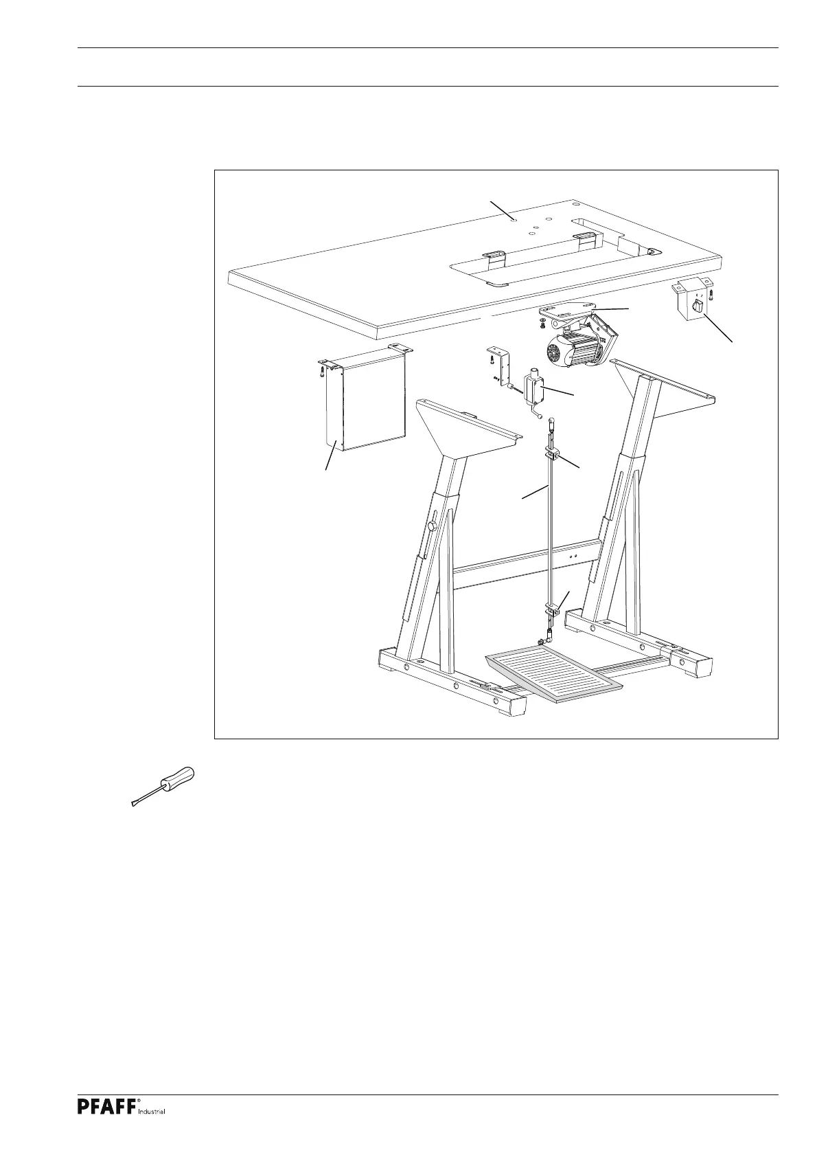
Fig. 4 - 02
4.02 Assembling the motor, speedcontrolunit and controlbox
4
.02.01 P45 PD2-L and P74 ED-L
1
M8x30 (3x)
6x30 (2x)
M8x30 (3x)
6x30 (2x)
6x30 (2x)
2
5
6
7
7
● Fasten the motor mounting 1 with motor to the screwed inserts 2 of the table top with
three hexagon bolts M8 x 30.
● Fit the control box 3 to the table top with four screws 6x30.
● Attach the mains switch 4 to the table top with two screws 6x30.
● Screw the mains cable of the control box 3 to the table top with a mains lead cleat.
● Assemble the speed control unit 4 and attach it to the table top with two screws 6x30.
● Mount the pedal on the stand’s cross-bar, aligning the middle of the pedal with the cen-
tre of the needle.
● Fit connection rod 5 to speed control unit 4 and to the pedal.
● The slant of the pedal can be adjusted after loosening screw 6 (slant angle approx. 10°).
3
6x30 (4x)
4
 Loading...