10
Adjustment
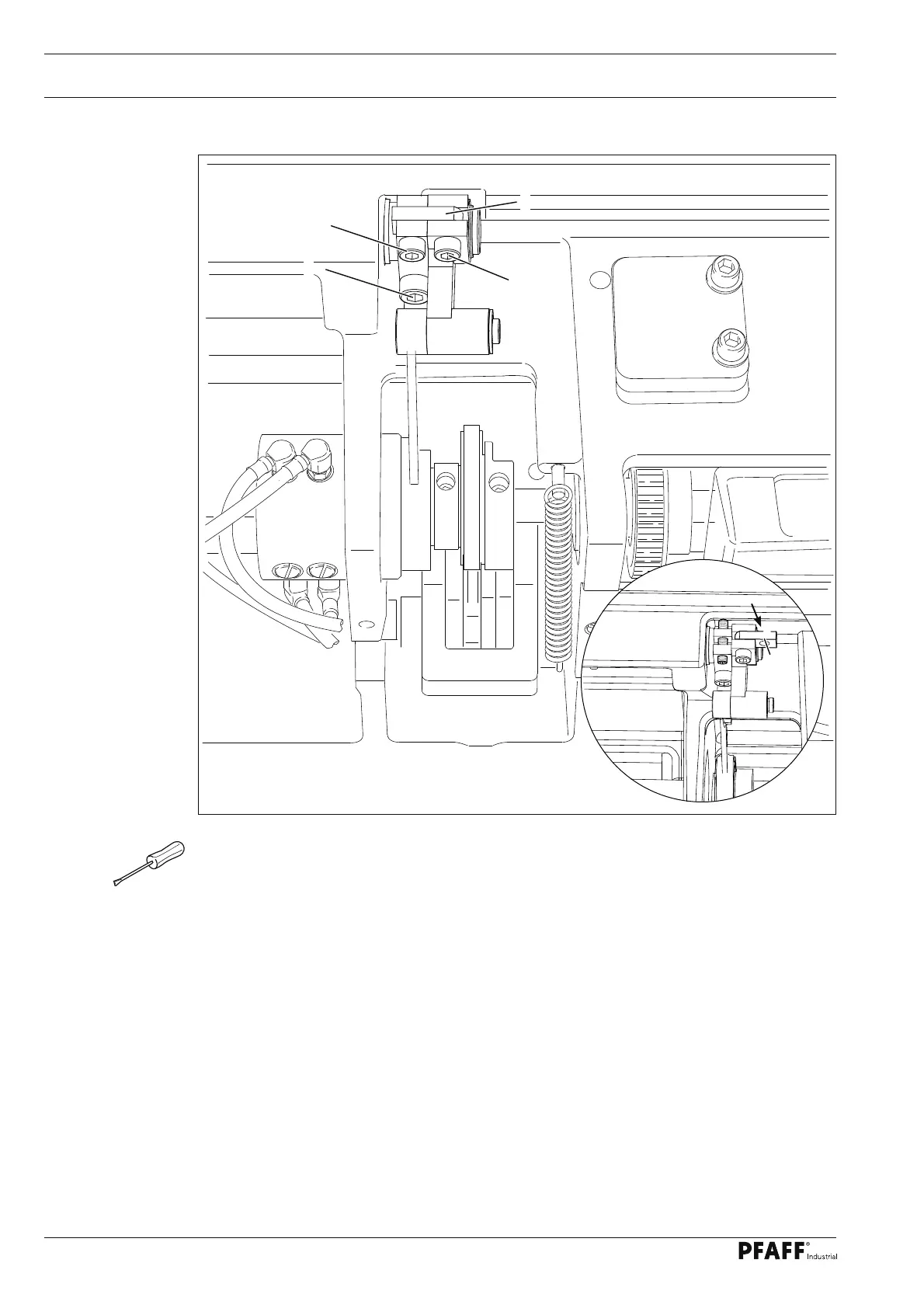
Fig. 1 - 05a
10
9
8
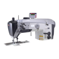
Activate lifting movement
Lifting movement is activated if connection part ● 8 is swiveled in as shon in
fi gures 1 - 05a, and screws 9 (M6 x 16) and 10 (M5 x 16) have been attached.
Deactivate lifting movement
Remov
e screws ● 9 and 10 and swivel connection part 8 (screw 11) towards the right.
Replace screw ● 9 with a screw M6 x 25.
Replace screw ● 10 with a threaded pin M5 x 25 and tighten to stop.
11
8
 Loading...