Short Instructions
Incl. Declaration of Conformity
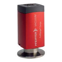
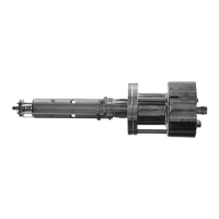
Compact FullRange™ BA
Gauge
PBR 260
BG 805 131 BE / A (2005-10)
Product Identification
In all communications with Pfeiffer Vacuum, please specify
the information on the product nameplate. For convenient re-
ference copy that information into the space provided below.
Pfeiffer Vacuum, D-35614 Asslar
Typ:
No:
F-No:
V W
Validity
This document applies to products with part number
PT R27 000
(DN 25 ISO-KF)
PT R27 001 (DN 40 ISO-KF)
PT R27 002 (DN 40 CF-R)
The part number (No) can be taken from the product name-
plate.
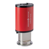
If not indicated otherwise in the legends, the illustrations in
this document correspond to the gauges with the vacuum
connection DN 25 ISO-KF. They apply to gauges with other
vacuum connections by analogy.
We reserve the right to make technical changes without prior
notice.
All dimensions in mm.
Intended Use
The PBR 260 Compact FullRange™ BA Gauge has been
designed for vacuum measurement of non-flammable gases
and gas mixtures in a pressure range 5×10
-10
… 1000 mbar.
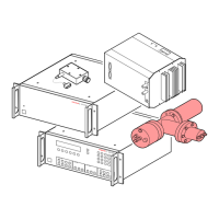
The gauge is a part of the Pfeiffer Vacuum Compact Gauges
family and can be operated in connection with the
MaxiGauge™ vacuum measurement and control unit or with
another evaluation unit.
Functional Principle
Over the whole measurement range, the PBR 260 Compact
FullRange™ BA Gauge has a continuous characteristic curve
and its measuring signal is output as logarithm of the pres-
sure.
The gauge functions with a Bayard Alpert hot cathode ioniza-
tion measurement system and a Pirani measurement system.
In a defined overlapping pressure range, a mixed signal of
the two measurement systems is output. Above that range, a
Pirani signal, below that range, a hot cathode signal is output.
The Pirani measurement system switches the hot cathode
measurement system on and off to prevent filament burn-out
and excessive contamination. Two switching on/off ranges
are available.
Trademarks
MaxiGauge™ INFICON GmbH
FullRange™ INFICON GmbH
Symbols Used
DANGER
Information on preventing any kind of physical injury.
WARNING
Information on preventing extensive equipment and en-
vironmental damage.
Caution
Information on correct handling or use. Disregard can lead
to malfunctions or minor equipment damage.
Personnel Qualifications
Skilled personnel
All work described in this document may only be carried out
by persons who have suitable technical training and the ne-
cessary experience or who have been instructed by the
end-user of the product.
General Safety Instructions
• Adhere to the applicable regulations and take the ne-
cessary precautions for the process media used.
Consider possible reactions between the materials
(→ "Technical Data") and the process media.
Consider possible reactions (e.g. explosion) of the process
media due to the heat generated by the product.
• Adhere to the applicable regulations and take the ne-
cessary precautions for all work you are going to do and
consider the safety instructions in this document.
• Before beginning to work, find out whether any vacuum
components are contaminated. Adhere to the relevant re-
gulations and take the necessary precautions when hand-
ling contaminated parts.
Communicate the safety instructions to all other users.
Liability and Warranty
Pfeiffer Vacuum assumes no liability and the warranty be-
comes null and void if the end-user or third parties
• disregard the information in this document
• use the product in a non-conforming manner
• make any kind of interventions (modifications, alterations
etc.) on the product
• use the product with accessories not listed in the corres-
ponding product documentation.
The end-user assumes the responsibility in conjunction with
the process media used.
Gauge failures due to contamination, as well as expendable
parts (filament), are not covered by the warranty.
Technical Data
Measurement range (air, N
2
)
5×10
-10
… 1000 mbar
Overlapping range hot
cathode – Pirani
high (default)
low
5.5×10
–3
… 2.0×10
–2
mbar
2.0×10
–3
… 8.0×10
–3
mbar
Accuracy
(10
-8
… 10
-2
mbar)
≈15 % measurement
(after 5 min. stabilization)
Repeatability
(10
-8
… 10
-2
mbar)
≈5 % measurement
(after 5 min. stabilization)
Emission of hot cathode
Switching on pressure (hi)
Switching off pressure (hi)
Switching on pressure (lo)
Switching off pressure (lo)
2.4×10
-2
mbar (default)
3.2×10
-2
mbar (default)
9.9×10
-3
mbar
1.3×10
-2
mbar
Emission current
(with decreasing pressure)
7.2×10
-6
mbar < p <
2.4×10
-2
mbar
p
≤ 7.2×10
-6
mbar
25 µA
5 mA
Emission current switching
25 µA
⇒ 5 mA (with
decreasing pressure)
5 mA
⇒ 25 µA (with
increasing pressure)
7.2×10
-6
mbar
3.2×10
-5
mbar
Degas
(only if p < 7.2×10
-6
mbar)
current approx. 16 mA / 4.0 W
control input signal 0 V / 24 V, PLC level,
high active
duration max. 3 min, followed by
automatic stop
In degas mode, the PBR 260 keeps supplying measure-
ment values the tolerances of which can be higher than
during normal operation.
Output signal (measuring
signal)
voltage range 0 ... 10.2 V
measurement range 0.774 V
… 10 V
(5×10
-10
mbar … 1000 mbar)
relationship voltage-
pressure
logarithmic,
0.75 V / decade
error signals
0.3 V
0.5 V
→ [1]
error hot cathode system
error Pirani system, elec-
tronics incorrectly mounted
to sensor
underrange
overrange
0.5 V
< U < 0.774 V
10 V
< U ≤ 10.2 V
(measuring signal limited to
10.2 V by software)
Minimum load
10 kΩ
Gauge identification
(U
max
= 4.25 V)
Resistor 17.2 kΩ referenced
to supply common
Adjustment
Pirani
HV
automatic adjustment by hot
cathode at 1 … 3×10
-3
mbar
ATM (<ATM> button) adjustment via ATM button
(keep button depressed for
at least 5 seconds) at at-
mospheric pressure
Zero point adjustment
(<ATM> button)
adjustment via ATM button
(keep button depressed for
at least 2 seconds) at
≤1×10
-4
mbar
Hot cathode factory adjusted, readjust-
ment not required
Supply
DANGER
The gauge may only be connected to supply and
evaluation units that conform to the requirements
of a grounded protective extra-low voltage
(SELV-E according to EN 61010). The connec-
tion to the gauge has to be fused.
1)
Voltage at gauge 20 … 28 VDC
2)
(max. ripple. 2 V
pp
)
Power consumption
standard
degas
emissions start (200 ms)
≤0.5 A
≤0.8 A
≤1.4 A
1)
The MaxiGauge™ fulfills these requirements.
2)
The minimum voltage of the power supply must be increased
proportionally to the length of the sensor cable.