Power consumption
≤16 W
Fuse to be connected
1)
≤1.25 AT
Voltage at the supply unit with
maximum cable length
21
… 28 VDC
(max. ripple. 2 V
pp
)
Electrical connection Hirschmann compact
connector GO 6,
6 contacts, male
Cable 5 poles plus screening
Cable length max. 35 m (0.25 mm² conductor)
50 m (0.34 mm² conductor)
100 m (1.0 mm² conductor)
Grounding concept → Figure 1
Materials on the vacuum
side
housing, supports,
screens
feedthrough
isolator
cathode
cathode holder
Pirani element
stainless steel
NiFe nickel plated
glass
iridium, yttrium oxide
molybdenum
tungsten, copper
Internal volume
DN 25 ISO-KF
DN 40 ISO-KF
DN 40 CF-R
≤ 24 cm
3
≤ 24 cm
3
≤ 34 cm
3
Pressure max. 2 bar (absolute)
Admissible temperatures
storage
operation
bakeout
–20 °C ... +70 °C
0 °C … +50 °C
150 °C (without electronics
unit or with extension)
Relative humidity
year’s mean
during 60 days
≤ 65% (no condensation)
≤ 85% (no condensation)
Use indoors only
altitude up to 2000 m
Type of protection IP 30
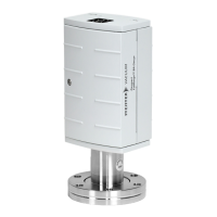
Dimensions [mm]
DN 25 KF
DN 40 KF
DN 40 CF-R
Weight 285 g (Flansch DN 25 ISO-KF)
315 g (Flansch DN 40 ISO-KF)
550 g (Flansch DN 40 CF-R)
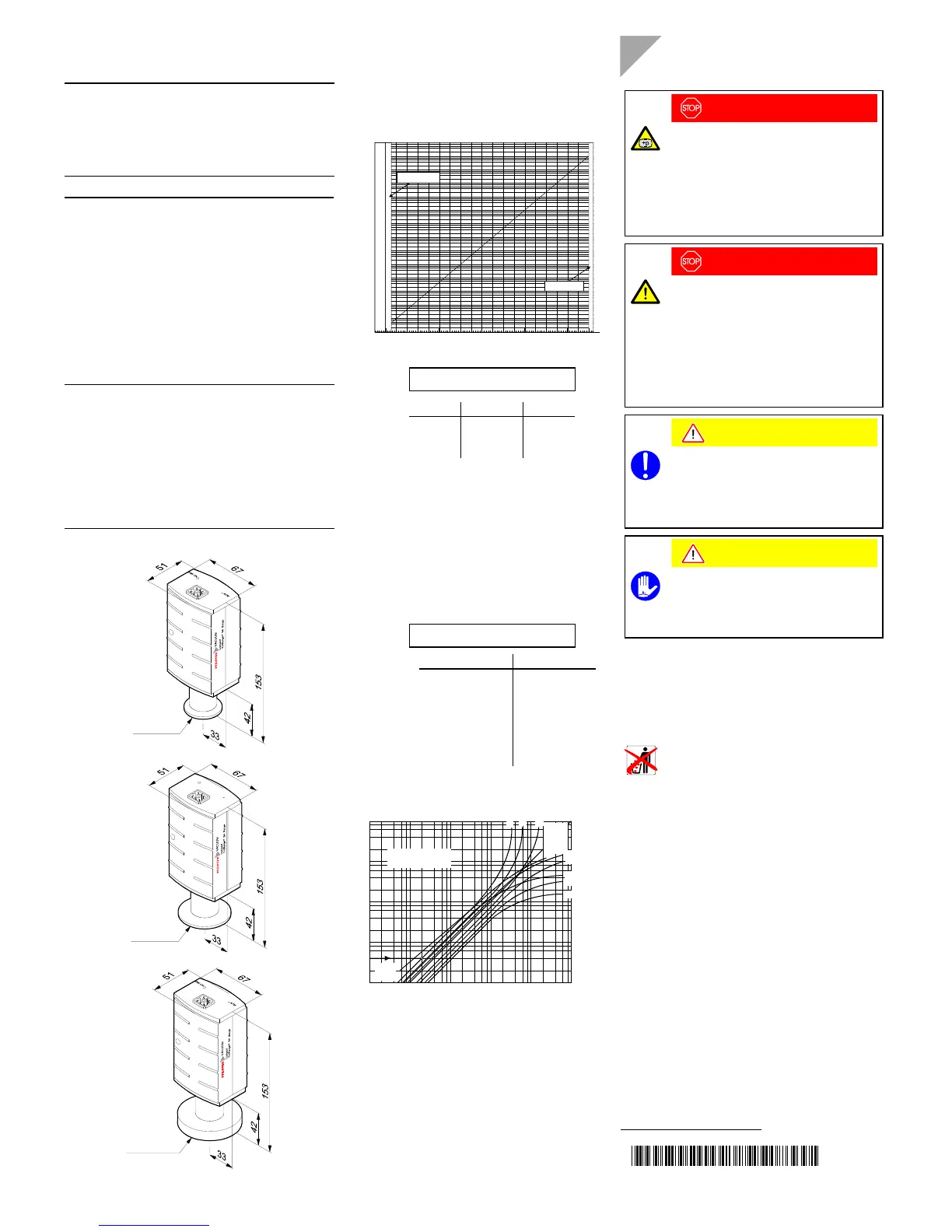
Measuring Signal vs. Pressure
Sensor error
overrange
underrange
1.0 2.0 3.0 4.0 5.0 6.0 7.0 8.0 9.0 10.0
1E+01
1E–01
1E–03
1E–05
1E–07
1E–09
1E+03
1E+04
1E+02
1E+00
1E–02
1E–04
1E–06
1E–08
1E–10
0.0
Measuring signal U[V]
Pressure p [mbar]
p = 10
(U-7.75)/0.75+c
Upc
[V] [mbar] 0
[V] [Pa] 2
[V] [Torr] -0.125
where valid in the range
p pressure
U measuring signal
c constant (pressure unit
dependent)
0.774 V
≤ U ≤ 10.000 V
Gas Type Dependence
Hot cathode range
For gases other than air, the pressure in the indication range
p < 10
-3
mbar can be determined by a simple conversion:
p
eff
= K × indicated pressure
where Gas type K (mean)
Air (N
2
, O
2
,
CO) 1.0
Xe 0.4
Kr 0.5
Ar 0.8
H
2
2.4
Ne 4.1
He 5.9
Pirani range
10
2
8
6
4
2
p (mbar)
p
eff
(mbar)
H
2
He
Ne
Xe
Kr
Ar
Freon 12
Luft / Air
O2
CO
N
2
10
–3
24
6
10
–2
10
–1
10
0
10
1
10
2
8
24
68
24
68
24
68 2 4 68
Water
vapor
Indication range
above 10
-2
mbar
CO2
10
1
8
6
4
2
10
0
8
6
4
2
10
-1
8
6
4
2
10
-2
Installation
Vacuum Connection
DANGER
Caution: overpressure in the vacuum system
>1 bar
Injury caused by released parts and harm
caused by escaping process gases can result if
clamps are opened while the vacuum system is
pressurized.
Do not open any clamps while the vacuum sys-
tem is pressurized. Use the type of clamps which
are suited to overpressure.
DANGER
Caution: hazardous voltages
Incorrectly grounded products can be extremely
hazardous in the event of a fault.
The gauge must be electrically connected to the
grounded vacuum chamber. This connection
must conform to the requirements of a protective
connection according to EN 61010:
• CF flanges fulfill this requirement.
• For gauges with a KF flange, use a conduc-
tive metallic clamping ring.
Caution
Caution: vacuum component
Dirt and damages impair the function of the
vacuum component.
When handling vacuum components, take
appropriate measures to ensure cleanliness and
prevent damages.
Caution
Caution: dirt sensitive area
Touching the product or parts thereof with bare
hands increases the desorption rate.
Always wear clean, lint-free gloves and use
clean tools when working in this area.
The gauge should be mounted so that no vibrations occur.
The gauge may be mounted in any orientation. However, any
particles and condensates present should not be able to
penetrate into the measuring chamber. Install the gauge in
such a way that it need not be removed for adjustment.
Remove the protective lid and install the product to the
vacuum system.
Keep the protective lid.
bg805131be/ a
(2005-10)
Original: German BG 805 131 BD / A (2005-10)
 Loading...