Power Connection
Precondition: Vacuum connection is properly made.
Before connecting or disconnecting the product, turn
off the control system.
If no sensor cable is available, make one according to
the diagram.
–
+
–
+
Figure 1: Electrical connection
Pin 1 a) Degas
b) Identification
(U
≤ 4.25 V)
Pin 2 Signal output
(measuring signal)
Pin 3 Signal common GND
Pin 4 Supply
Pin 5 Supply common GND
Pin 6 Screening
2
5
3
1
6
4
Connector,
soldering side
Connect the signal cable to the gauge and secure it
with the screw.
Connect the gauge to the measurement and control
unit.
Operation
When the voltage is applied, the measuring signal is avail-
able between pins 2 and 3. Over the whole measurement
range, the measuring signal is output as a logarithm of the
pressure (Relationship between measuring signal and pres-
sure
→ "Technical Data").
Allow for a stabilizing time of approx. 10 minutes. Once the
gauge has been switched on, permanently leave it on irre-
spective of the pressure.
Gas Type Dependence
The measurement value is gas dependent. The display ap-
plies to dry air, N
2
, O
2
and CO. For other gases, it has to be
converted (
→ "Technical Data").
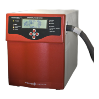
If the gauge is operated in connection with a MaxiGauge™
vacuum measurement and control unit, a calibration factor
can be entered for correction of the reading (
→ [2]).
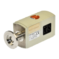
Measurement Range
The PBR 260 covers the measurement range of
5×10
-10
mbar … 1000 mbar.
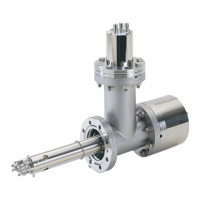
• The Pirani system continuously monitors the pressure.
• The hot cathode system (controlled by the Pirani) is only
switched on when the pressure drops below the set
threshold (p
on
). The hot cathode will be ready for operation
after a few seconds' heating time, when the <EMI ON>
lamp is lit.
• When the pressure rises above the setpoint (p
off
) the hot
cathode is switched off and the <EMI ON> lamp turns off.
In the upper pressure range, the Pirani reading and in the
lower pressure range, the hot cathode reading is output. In
the overlapping range (p
lower
… p
upper
), a combined signal of
the two measurement systems is supplied:
1000 mbar5 ×
10
-10
mbar
PiraniHot cathode
p
u
p
p
e
r
p
l
o
w
e
r
p
o
n
p
o
f
f
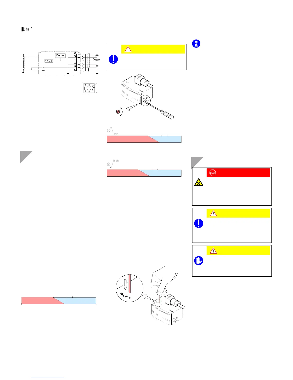
Defining the Switching on/off Range
The PBR 260 has two definable switching on/off ranges with
their corresponding overlapping ranges. The switching on/off
range is selected with the <P
↔ BA> switch and should be
chosen in such a way that it is situated outside the process
pressure range. The positions "high" (default) and "low" are
available. Preferably, "low" should be selected as contamina-
tion of the hot cathode system is reduced at lower pressures.
Caution
The switching on/off range must be selected
before the gauge is activated as the switch
position is polled only when the gauge is
switched on.
high
low
5 ×
10
-10
mbar
5
.
5
×
1
0
-
3
2
.
4
×
1
0
-
2
3
.
2
×
1
0
-
2
2
.
0
×
1
0
-
2
1000 mbar
high
5 ×
10
-10
mbar
2
.
0
×
1
0
-
3
9
.
9
×
1
0
-
3
1
.
3
×
1
0
-
2
8
.
0
×
1
0
-
3
1000 mbar
low
PiraniHot cathode
PiraniHot cathode
Adjusting the Gauge
The gauge is factory calibrated. If used under different cli-
matic conditions or in a different position, through aging or
contamination, and after exchanging the sensor, the charac-
teristic curve can be offset and readjustment can become
necessary. Only the Pirani element can be adjusted. The hot
cathode system is factory adjusted.
HV adjustment:
At p ≈ 2×10
-3
mbar the Pirani system is automatically adjusted
by the hot cathode.
Adjustment at atmospheric pressure:
Operate the gauge for 10 minutes at atmospheric
pressure. If the gauge was operated within the hot
cathode range, a cooling-down time of approx.
30 minutes is to be expected (gauge temperature =
ambient temperature).
Insert a pin through the opening marked <ATM> and
push the button inside for at least 5 s.
Zero point adjustment:
A zero point adjustment is recommended
• after the sensor has been exchanged
• as part of the usual maintenance work for quality
assurance.
The push button used for the adjustment at atmospheric
pressure is also used for the zero point adjustment.
Operate gauge for approx. 10 minutes at a pressure of
≤1×10
-4
mbar.
Insert the pin through the opening marked <ATM> and
push the button inside for at least 2 s..
The adjustment is done automatically and ends after
2 minutes.
Degas
Deposits on the electrode system of the hot cathode ioniza-
tion gauge can lead to unstable measurement readings.
In such a case it is advisable to start a degas process of the
anode (bakeout) at a pressure below 7.2×10
-6
mbar (5 mA
emission current). Depending on the application, this function
can be activated via a MaxiGauge™ vacuum measurement
and control unit, manually with a switch, or automatically by
the system control (e.g. PLC). The bakeout process is auto-
matically stopped by the PBR 260 after 3 minutes, if it has not
been terminated before.
The degas process is activated when the control signal
(Pin 1) switches from OFF (0 V) to ON (24 V). It is deacti-
vated when the control signal switches from ON (24 V) to
OFF (0 V), or after a maximum of 3 minutes.
For a repeated degas process, the control signal first has to
switch from ON (24 V) to OFF (0 V), to then start the degas
process again with ON (24 V). If the degas function is acti-
vated by the system control, it should be set to OFF again by
the system control after max. 3 minutes of bakeout in order
for an unambiguous operating status to be achieved.
The degas process causes a heating of the electron collector
grid to approx. 700 °C by electron bombardment.
Deinstallation
DANGER
Caution: contaminated parts
Contaminated parts can be detrimental to health
and environment.
Before beginning to work, find out whether any
parts are contaminated. Adhere to the relevant
regulations and take the necessary precautions
when handling contaminated parts.
Caution
Caution: vacuum component
Dirt and damages impair the function of the
vacuum component.
When handling vacuum components, take
appropriate measures to ensure cleanliness and
prevent damages.
Caution
Caution: dirt sensitive area
Touching the product or parts thereof with bare
hands increases the desorption rate.
Always wear clean, lint-free gloves and use
clean tools when working in this area.
Vent the vacuum system.
Turn the gauge off.
Unplug the sensor cable.
Remove the gauge from the vacuum system and install
the protective lid.
 Loading...