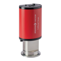
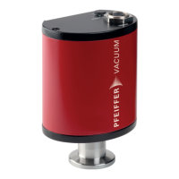
The PPT 200 is a digital Pirani gauge designed for measuring pressure in vacuum systems. It operates based on the principle of heat conduction, specifically using a Pirani sensor, and is calibrated to nitrogen (N2) or dry air. The device is designed for individual applications, offering maximum performance and reliability.
Function Description
The PPT 200 gauge measures pressure by detecting the heat conduction of the gas. The measuring signal is available at the electrical connection once the supply voltage is established. Pressure values are transferred in an "aaaabb" format, where "aaaa" represents the mantissa (ranging from 1000 to 9999) and "bb" is the exponent with an offset of 20. The device communicates via an RS-485 interface, allowing for control and data acquisition through a Pfeiffer Vacuum display and control unit or a PC.
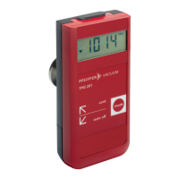
The gauge features an LED display that indicates its operating mode:
- Off: No power supply.
- Lights up green: Supply voltage OK, measuring mode, valid pressure values.
- Lights up yellow: Other mode (e.g., Zero Adjust), measuring range exceeded/undershot, temporarily no valid measured values.
- Lights up red: Software or gauge error.
- Lit for 1 s green, yellow and red: LED test after commissioning or reset.
- Flashing red/green (1 Hz): Software update in progress.
The measuring signal of the gauge is dependent on the type of gas. A correction factor can be applied to compensate for this dependency when measuring gases other than the calibration gas (nitrogen or dry air). The effective pressure (Peff) can be calculated using the formula: Peff = C x p, where C is the correction factor and p is the displayed pressure.
Important Technical Specifications
Measured and Pressure Values:
- Measuring range (air, O2, CO, N2): 1 x 10⁻⁴ – 1000 hPa
- Maximum pressure (absolute): 4000 hPa
- Measuring principle: Heat conduction according to Pirani
- Measuring cycle: 10 ms
- Accuracy (N2):
- < 2 x 10⁻³ hPa: < Factor 2
- 2 x 10⁻³ – 20 hPa: ±10% of the measured value
- 20 – 1000 hPa: ±30% of the measured value
- Repeatability (2 x 10⁻³ – 10 hPa): ±2% of the measured value
- Gauge calibration: via RS-485 interface
Electrical Data:
- Supply voltage: 24 V DC
- Power consumption: 2.5 W
- Connection (electrical): Binder M12 connector, 5-pole, A-coded
- Cable length: ≤100 m
- Protocol: ASCII, addressable (RS-485), Pfeiffer Vacuum protocol
- Data format: Bidirectional data traffic, data word length 8 bits, 1 stop bit, no parity bit
- Baud rate: 9600
- Connection (RS-485 interface): Binder M12 connector, 5-pole, A-coded
Connection Flanges and Weight:
- DN 16 ISO-KF: 190 g
- DN 16 CF-F: 220 g
Ambient Conditions:
- Air pressure: 800 – 1060 hPa
- Relative humidity of air:
- At temperatures up to +30°C max. 80%
- At temperatures up to +40°C max. 50%
- Non-condensing
- Mounting orientation: Arbitrary
- Usage: Only in indoor areas
- Installation altitude max.: 2000 m MSL
- Protection degree: IP54
Temperatures:
- Operation: +5 – +60 °C
- Bake out (vacuum connection): 150 °C
- Storage: -40 – +65 °C
Materials (Substances in contact with media):
- Stainless steel
- Tungsten
- Glass
Usage Features
Installation:
- The gauge should be mounted in a horizontal to upright orientation (flange facing downwards) to prevent condensate and particles from accumulating in the measurement chamber.
- A seal with a centering ring and filter is recommended for applications susceptible to pollution.
- It is important to ensure the gauge is not exposed to vibrations during operation, as this can lead to deviations in measured values.
- For RS-485 connections, always interrupt the voltage supply before plugging in or unplugging the power supply plug to prevent damage to electronic components. Wait until the residual load has dispersed completely after switching off the power supply pack.
Operation:
- A minimum stabilization period of 10 minutes is recommended after power-up.
- The gauge should be left switched on at all times, regardless of the applied pressure.
- The device allows reading of various parameters via the RS-485 interface, including current pressure value ([P:740]), error code ([P:303]), firmware version ([P:312]), device name ([P:349]), hardware version ([P:354]), serial number ([P:355]), and order number ([P:388]).
- Pressure switch points can be set via parameters [P:730] and [P:732].
- The Pirani correction factor can be read and set via parameter [P:742].
Safety Precautions:
- Electrical Safety: Only connect the product to devices meeting PELV (earthed protective extra-low voltage) and LPS Class 2 requirements. Secure the line to the product. Avoid voltages exceeding specified safety extra-low voltage to prevent damage to insulation and electric shock.
- Moisture Ingress: Operate the unit only in a dry environment, away from fluids and moisture sources. Do not switch on the unit if fluid has entered it; contact Pfeiffer Vacuum Service instead.
- Overpressure: Do not open any tensioning pieces when overpressure > 1000 hPa is present in the vacuum system. Use suitable tensioning pieces and sealing rings with an outer centering ring to prevent injury from flying parts or escaping process medium. Elastomer seals are not resistant to pressures > 2500 hPa.
- Contaminated Products: If the product has been in contact with toxic or harmful substances, take appropriate safety precautions during maintenance and shipping. Decontaminate affected parts and wear protective equipment.
- Cleaning Agents: Use only industrial alcohol and a soft, lint-free cloth for cleaning. Do not use solvents or aggressive/abrasive cleaning agents.
Maintenance Features
Cleaning the Transmitter:
- External cleaning: Use a cloth soaked in industrial alcohol and allow surfaces to dry thoroughly.
- Cleaning measuring chamber:
- Remove the gauge from the vacuum system.
- Fill the measuring chamber with industrial alcohol.
- Allow 5 minutes for the alcohol to take effect.
- Drain the alcohol from the chamber.
- Allow the chamber to dry well (at least 10 minutes).
- Reconnect the gauge to the vacuum system.
Calibrating the Gauge:
- Preparing for calibration:
- Put the gauge into operation.
- Ensure the installation and ambient conditions are normal.
- Check for filter contamination.
- Replace the filter if contaminated or damaged.
- Put the gauge into operation.
- Performing calibration with display and control unit: Calibrate the gauge according to the operating instructions for the display and control unit.
- HV calibration:
- Put the gauge into operation.
- Evacuate the vacuum system to pressure << 1x10⁻⁵ hPa.
- Wait for at least 10 minutes.
- Via parameter [P:741], set the pressure adjustment point to "000" for low pressure.
- Via parameter [P:740], set the pressure value to "000000" for low pressure.
- ATM calibration:
- Put the gauge into operation.
- Operate the gauge for at least 10 minutes at atmospheric pressure.
- Via parameter [P:741], set the pressure adjustment point to "001" for high pressure.
- Via parameter [P:740], set the pressure value to atmospheric pressure.
Replacing the Sensor Module:
- The sensor module can be replaced if it is heavily contaminated, the sensor is defective, or the sensor filament is broken.
- Required tools: Torx wrench, T 6.
- Procedure:
- Remove the gauge from the vacuum system.
- Loosen the Torx screws and sealing washers.
- Carefully remove the sensor from the housing.
- Carefully insert the new sensor into the housing.
- Pay attention to the contact pins of the plug-and-socket connection.
- Fasten the Torx screws and sealing washers. The sealing washers regulate the protection class of the gauge.
- Reconnect the gauge to the vacuum system.
- Establish the electric connection.
- Calibrate the gauge.
Warranty:
- Malfunctioning of the equipment as a direct result of contamination or wear, as well as wear parts, is not covered by the warranty.
Shipping and Disposal:
- For shipping, comply with instructions for safe distribution, especially for contaminated products. Do not ship microbiological, explosive, or radioactively contaminated products.
- For disposal, follow general disposal information and dispose of gauges according to regulations. Components should be dismantled, decontaminated, and separated into recyclable materials.