4.2.2 Establishing mains connection
Procedure
1. Attach the air cooling to the pump bottom part in accordance with the 24 V/DC variants of the
same pump type.
2. If necessary, configure the accessory output for the air cooling via the interfaces of the electronic
drive unit.
–
The specification for the air cooling is "accessory A1".
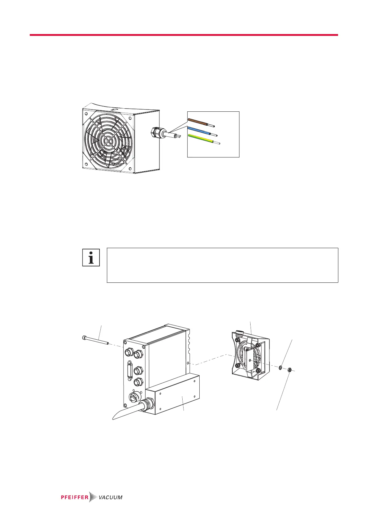
Fig. 10: Mains connection
Procedure
►
Ensure the correct supply voltage.
►
Configure the open cable connection according to the mains voltage specified on the rating plate.
►
Always ensure a secure connection to the earthed conductor (PE), protection class I.
4.3 Connecting the air cooling, 24 V DC for TeleTC
Recommended use of air cooling on the electronic drive unit
With commensurate ambient temperatures, Pfeiffer Vacuum recommends that an addition-
al air cooling be fitted on the TC of the turbopump.
●
Use the Y-distributor from the range of accessories as a connection for the air cooling.
Required tools
●
Open-end wrench, WAF 7
●
Allen key, WAF 3
Fig. 11: Mounting the air cooling to the electronic drive unit TC 400
1 Interior hexagon socket screw 4 Hexagon nut
2 Air cooling 5 TC adapter
3 Lock washer
Installation
16/26