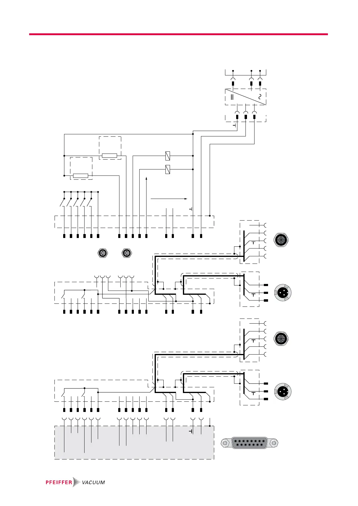
Fig. 3: Connection diagram and assignment of the TC 110
+U
B
PE
A
B
C
+U
B
PE
A
B
C
DC in DC in
1
2
3
4
5
24 VDC*
RS 485 +
RS 485 -
n.c.
1
2
3
4
5
24 VDC*
RS 485 +
RS 485 -
n.c.
RS485 RS485
2
3
4
5
6
7
10
11
8
9
12
13
14
15
1
1
8
9
15
X3
TC 110
DI Remote Priority
DI1
DI2
DI Pumping station
DI Standby
24 VDC* (V+)
Accessory A1
Accessory B1
DO1
DO2
AO1
RS 485 D+
RS 485 D-
+U
B
FE
34
21
A
B
C
X3
2
3
4
5
6
7
10
11
8
9
12
13
14
15
1
S2
S1
S2
S1
2
3
4
5
6
7
10
11
8
9
12
13
14
15
1
1
3
4
1
3
4
Acc. A1
Acc. B1
34
21
A
B
C
4
31
4
31
X3
Connection cable
TC 110 - TPS/DCU, RS485
TPS 110 / 180 and DCU 002 / HPU 001
or
DCU 110 / 180
Connection cable TC 110 - TPS/DCU
with accessory ports, RS485
TPS 110 / 180 and DCU 002 / HPU 001
or
DCU 110 / 180
0 - 10 VDC
= 0 - 100 % *f
end
R ≥ 10kΩ
90 - 132 /
185 - 265
VAC
2
3
4
5
6
7
10
11
8
9
12
13
14
15
1
+U
B
PE
B
A
C
TPS 110 / 180
DCU 110 / 180
X3
24 VDC / max. 200 mA
24 VDC / max. 200 mA
24 VDC / max. 50mA
24 VDC / max. 50mA
+24 VDC / 4,6 - 6,3 A ± 5 %
FE
DC out AC in
Contact current max. 6 mA / contact
Mains input /
Power supply
External connection
Fan
Venting
valve
Relay
Fan
Venting
valve
Relay
 Loading...