EasyManuals Logo

Pfeiffer TC 110 User Manual

Pfeiffer TC 110
34 pages
To Next Page IconTo Next Page
To Previous Page IconTo Previous Page
Page #9 background imageLoading...
Page #9 background image
Product description
9
3.3 Function
3.4 General connection description
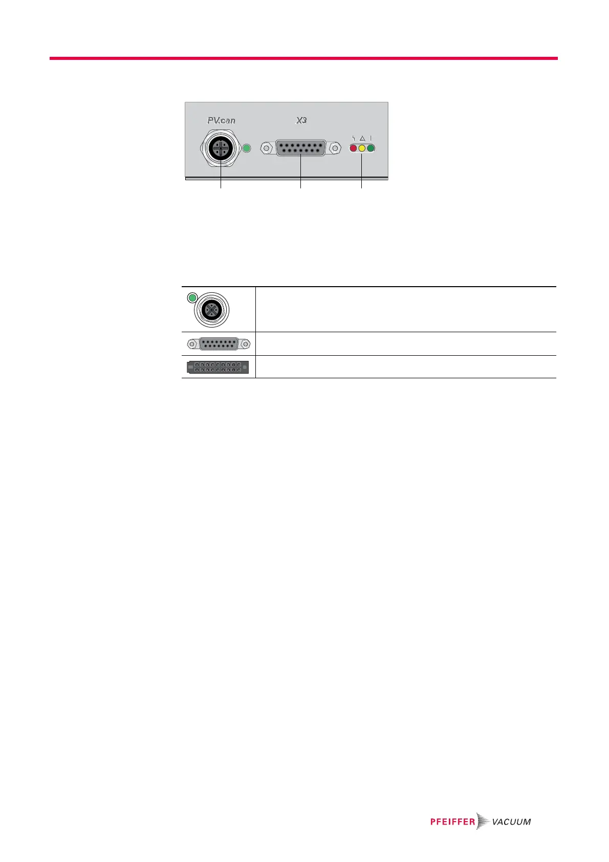
Fig. 2: Standard panel for the TC 110
c Connection "X3"
d Service connection "PV.can"
h LED "Operating display"
cd h
PV.can
M12 casing socket with screw coupling and LED for the connection of an integrated
pressure measurement and for Pfeiffer Vacuum Service purposes.
X3
D-sub 15 pole female socket for the connection of a remote control.
Casing socket on the rear side of the electronic drive unit for the connection to the
turbopump.

Questions and Answers:

Question and Answer IconNeed help?

Do you have a question about the Pfeiffer TC 110 and is the answer not in the manual?

Pfeiffer TC 110 Specifications

General IconGeneral
BrandPfeiffer
ModelTC 110
CategoryControl Unit
LanguageEnglish

Related product manuals