Connection "X3"
11
5 Connection "X3"
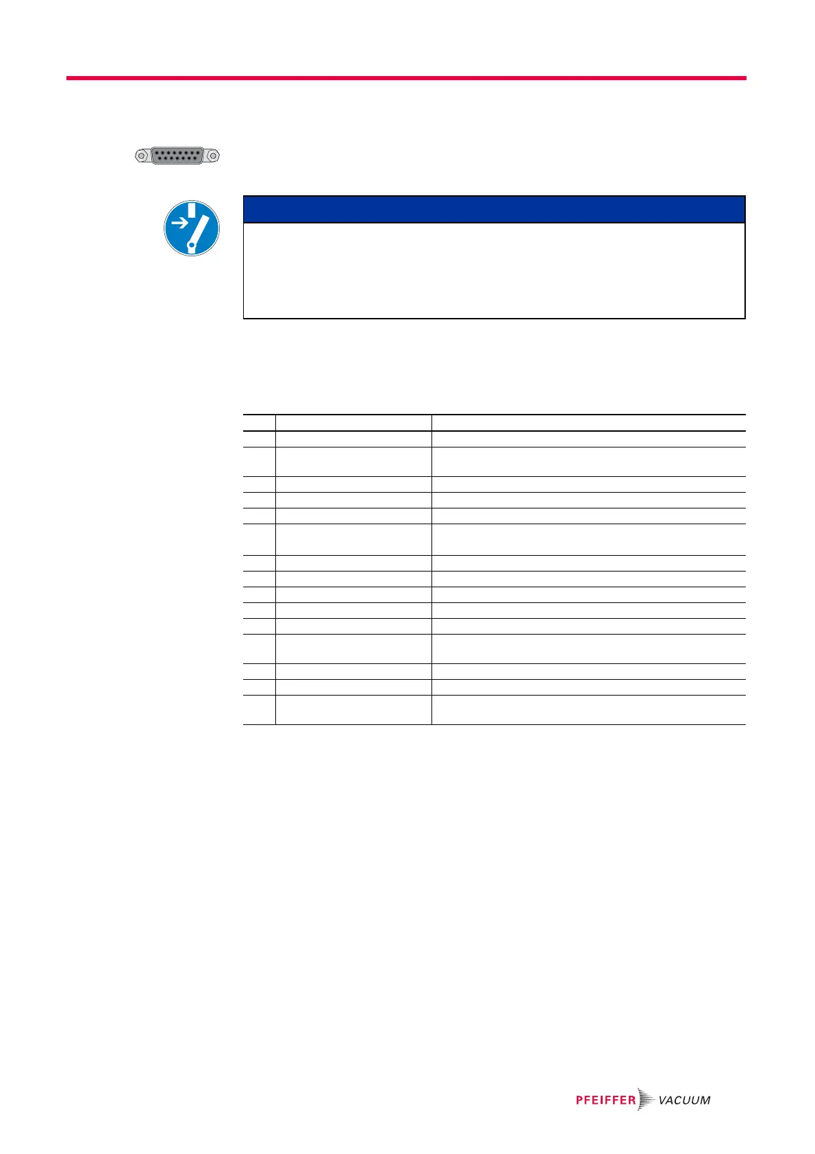
Remote control options and voltage supply are provided via the 15-pole D-sub connector
with the designation ”X3“ on the TC 110.
Shielded connectors and cables must be used.
The following information display the factory setting. Configuration is possible
using the Pfeiffer Vacuum parameter set.
5.1 Pin assignment
5.2 Operation via "X3" connection
5.2.1 Voltage supply
+24 V DC Input / Pin 1
The electrical connection at "X3" is carried out via connecting cables of the Pfeiffer Vac-
uum accessories program or by customized configuration on Pin 1 and Pin 15.
+24 V DC* Output / Pin 7
Inputs 2 - 6 are activated by connecting them with +24 V DC to Pin 7 (active high). They
can also be activated via an external PLC. The functions are deactivated by "PLC high
level" and by "PLC low level".
● PLC high level: +13 V to +33 V
● PLC low level: -33 V to +7 V
● Ri: 7 kΩ
● I
max
< 200 mA (with RS-485, if existing)
NOTICE
Danger of the drive unit being destroyed
Cutting the plug connection "X3" can lead to the destruction of the electronic drive unit,
when the power supply is still switched on.
Before pulling the connector "X3" necessarily disconnect the power supply.
Switch off the power supply unit.
Pin Function Designation factory settings
1 +24 V DC input Voltage supply for the electronic drive unit
2 DI Remote priority Control via interface "X3"; open: off;
V+: set and priority over other digital inputs
3 DI1 Enable venting; open: off; V+: on
4 DI2 Heating; open: off; V+: on
5 DI Pumping station open: off; V+: on and error acknowledgement
6 DI Standby
DI Error acknowledgement
Standby rotation speed; open: off; V+: on
Error acknowledgement: V+ pulse (500 - 2000 ms)
7 +24 V DC* output (V+) Reference voltage for all digital inputs
8 DO1 GND: no; V+: yes (I
max
= 50 mA/24 V)
9 DO2 GND: no; V+: yes (I
max
= 50 mA/24 V)
10 Accessory output A1 open: off; V+: on
11 Accessory output B1 open: off; V+: on
12 AO1 Actual rotation speed;
0-10 V DC is equivalent to 0-100%; R
L
> 10 kΩ
13 RS-485 D+
14 RS-485 D-
15 Ground (GND) Ground connection for the elctronic drive unit;
Reference ground for all digital inputs and all outputs
 Loading...