22
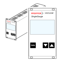
The Pfeiffer Vacuum parameter set
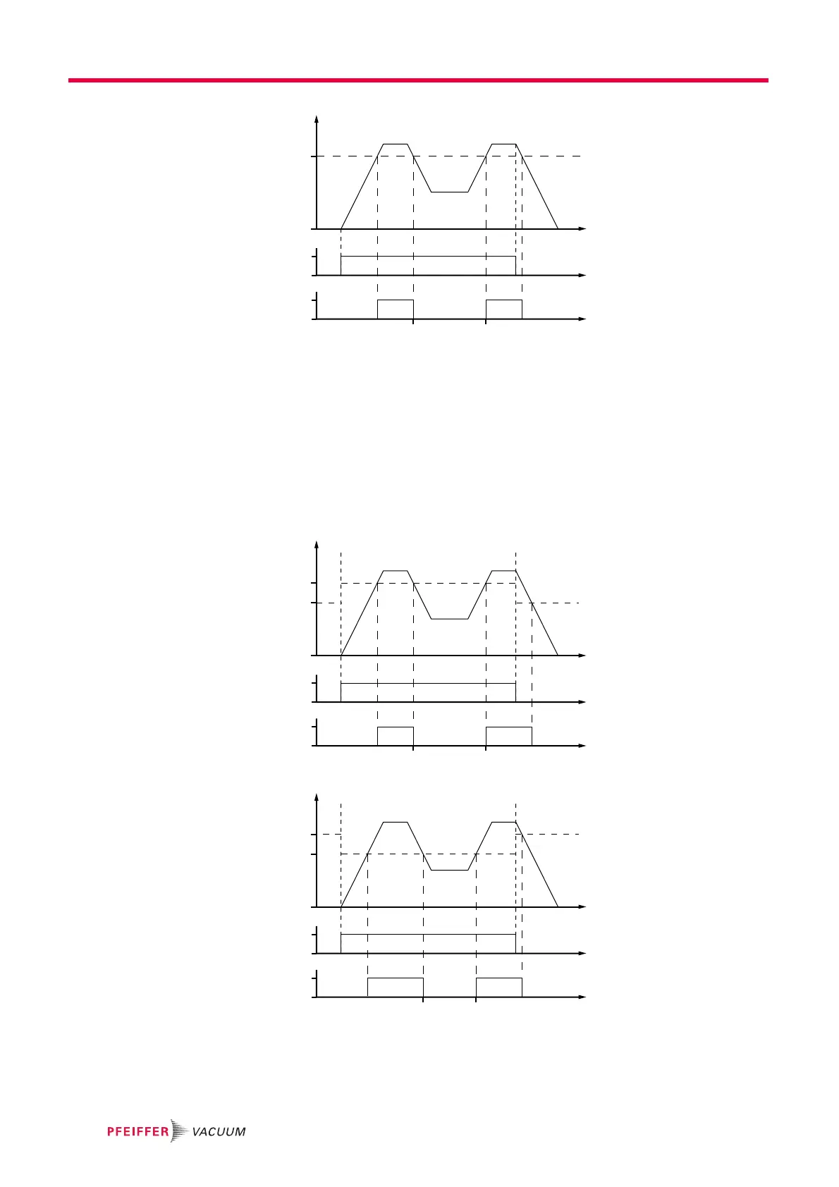
Fig. 7: Example for the configuration rotation speed switchpoint 1 active
Rotation speed switchpoint 1 & 2
Adjust the parameter [P:701] to the desired value in %.
Adjust the parameter [P:719] to the desired value in %.
Parameter [P:017] = 1
When the pumping station [P:010] is switched on, the rotation speed switchpoint 1 is the
signal generator. When the pumping station is switched off, signal output and status que-
ry are based on the rotation speed switchpoint 2. The signal output is governed by the
hysteresis between the two switchpoints.
Fig. 8: Example for the configuration rotation speed switchpoint 1+2 active; [P:701] > [P:719]
Fig. 9: Example for the configuration rotation speed switchpoints 1+2 active; [P:701] < [P:719]
Process
f
(%)
t
t
t
[P:010]
[P:302]
[P:701]
[P:017] = 0
0
1
0
1
Process
f
(%)
t
t
t
[P:010]
[P:302]
[P:701]
[P:719]
[P:017] = 1
0
1
0
1
Process
f
(%)
t
t
t
[P:010]
[P:302]
[P:719]
[P:701]
[P:017] = 1
0
1
0
1
 Loading...