19. Insert sealing*) and three bolts M8x45 into the bell
flange.
*)If included in scope of delivery (design-specific).
20. Push shrink tubing*) over cable.
*) If included in scope of delivery (design-specific).
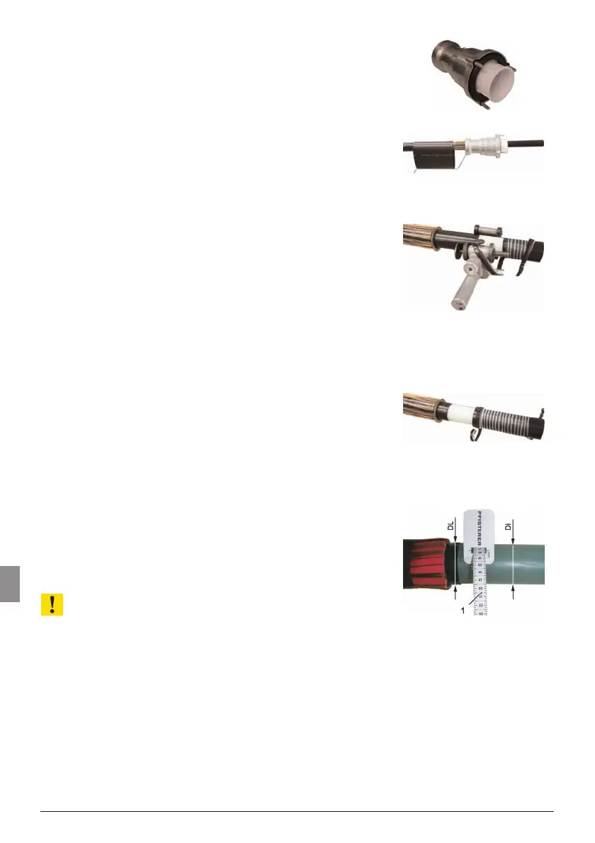
21. Push bell flange over cable.
In case of extruded fully bonded semi-conducting layer:
22. Push stop ring against jacket cut.
23. Set spacer of circular peeling device to 30 mm .
24. Set circular peeling device so that as little as
possible material is peeled off the insulation
(white).
25. Peel extruded fully bonded semi-conducting layer up
to 30 mm from the jacket cut.
26. Remove peeled-off semi-conducting layer.
27. Remove stop ring.
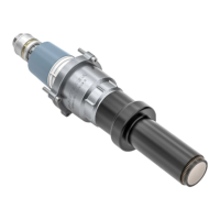
28. Determine diameter using the enclosed tape
measure (1):
DL Diameter of conducting layer
Di Diameter of insulation
ATTENTION!
The diameter of the insulation (Di) must lie within
the diameter range of the insulating part (see specifi-
cation in the insulating part neck)
29. Determine difference between DL and Di:
– DL – Di < 3,5mm
continue with step no. 30.
– DL – Di > 3,5mm
continue with subsequent steps a) to g).
20 Assembly / Installation PFISTERER CONNEX cable connector Size 3 and 3/S