PG DRIVES TECHNOLOGY AC TRACTION – INSTALLATION
6.2 Motor Connections
The three motor connections are marked M1, M2 and M3. There is no convention as to how these relate to the phase windings
on individual motors, so the controller to motor connections are arbitrary. If, when a forward command is applied, the vehicle
drives in reverse, swap any two of the motor connections.
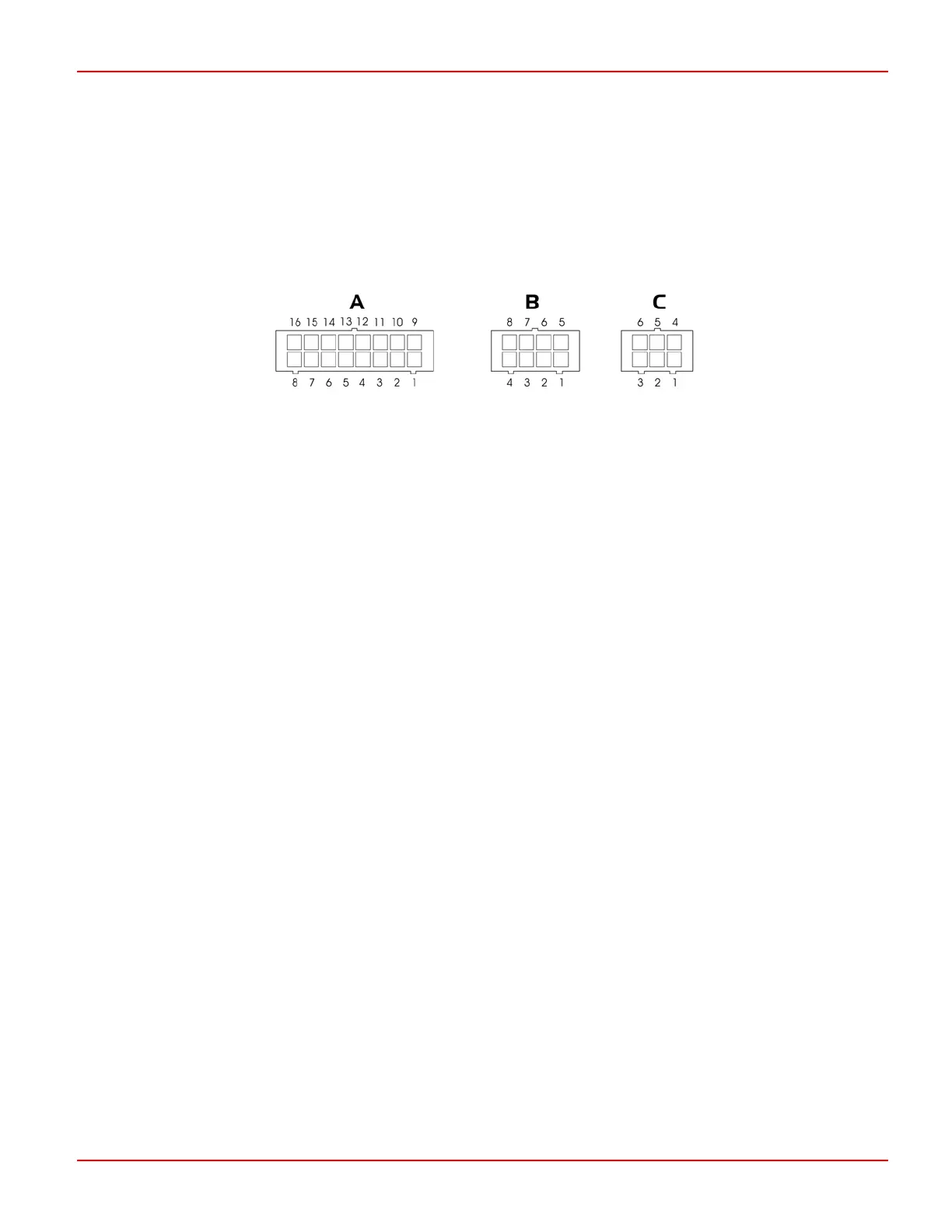
6.3 Control Connections
The control connections are via three connectors with pin-outs as follows.
Connector A: Vehicle Interface
Connector B: Communications to display module and/or programmer
Connector C: Motor Feedback
Details of the functions of each of the pins for these connectors are shown in the following section.
6.4 Connector ‘A’ – Vehicle Interface (16-way)
Pin 1 – Forward Switch
This switch must be closed in conjunction with the Accelerator to give a forward drive signal.
Pin 2 – Reverse Switch
This switch must be closed in conjunction with the Accelerator to give a reverse drive signal.
Pin 3 – Footswitch / Belly Button
The function of this input is set by the programmable parameter, 3.8 Truck Type Select.
If set to Ride, then the vehicle’s Footswitch should be connected to this pin, and must be closed to allow drive.
If set to Wlk, then the vehicle’s Belly Button switch should be connected to this pin. When the Belly Button switch is closed,
the vehicle will drive in the opposite direction for 1.5s.
Pin 4 – Seat / Tiller
The function of this input is to provide a general safety interlock. This could be a Seat switch on a ride-on vehicle, a Tiller
switch on a “walkie” vehicle or a general deadman’s trigger on other vehicle types. The switch must be closed to allow
drive.
Pin 5 – Speed Limit 1 / Inch Forward
The function of this input is set by the programmable parameter, 3.5 Connector A Pin 5 and 6.
If set to Spd, then this input can be used to limit the speed of the vehicle to a value set by the programmable parameter,
1.6 Speed Limit 1. The speed limit will occur when the switch is open.
SK79646-01 19