PG DRIVES TECHNOLOGY AC TRACTION – INSTALLATION
When set to 0, the active range of the footbrake input is defined by the programmable parameters, 1.23 Footbrake 0%
Voltage and 1.24 Footbrake 100% Voltage. The former parameter sets the voltage that relates to zero braking demand
from the Footbrake, while the latter parameter sets the voltage that relates to 100% braking demand from the Footbrake.
If a Footbrake switch is used on the brake pedal instead of an analogue device, the switch should connect this input to
the voltage corresponding to the value of parameter, 1.24 Footbrake 100% Voltage, in order to effect full braking.
When set to 1, the active range of the accelerator input is defined by the programmable parameters, 1.21 Accelerator
0% Voltage and 1.22 Accelerator 100% Voltage. The former parameter sets the voltage that relates to zero drive demand
from the Accelerator, while the latter parameter sets the voltage that relates to 100% drive demand from the Accelerator.
When set to 2, the active range of the throttle input is defined by the programmable parameters, 1.21 Accelerator 0%
Voltage, 1.22 Accelerator 100% Voltage, 1.28 Forward Threshold and 1.29 Reverse Threshold. Parameter 1.21 sets the
voltage that relates to 100% reverse drive demand from the Throttle, while parameter 1.22 sets the voltage that relates to
100% forward drive demand from the Throttle. Parameters 1.28 and 1.29 set the neutral ‘dead band’.
If the operation of the wig-wag pot is reversed, swap the two supply leads of the potentiometer.
Transposing the parameter values will result in a fault.
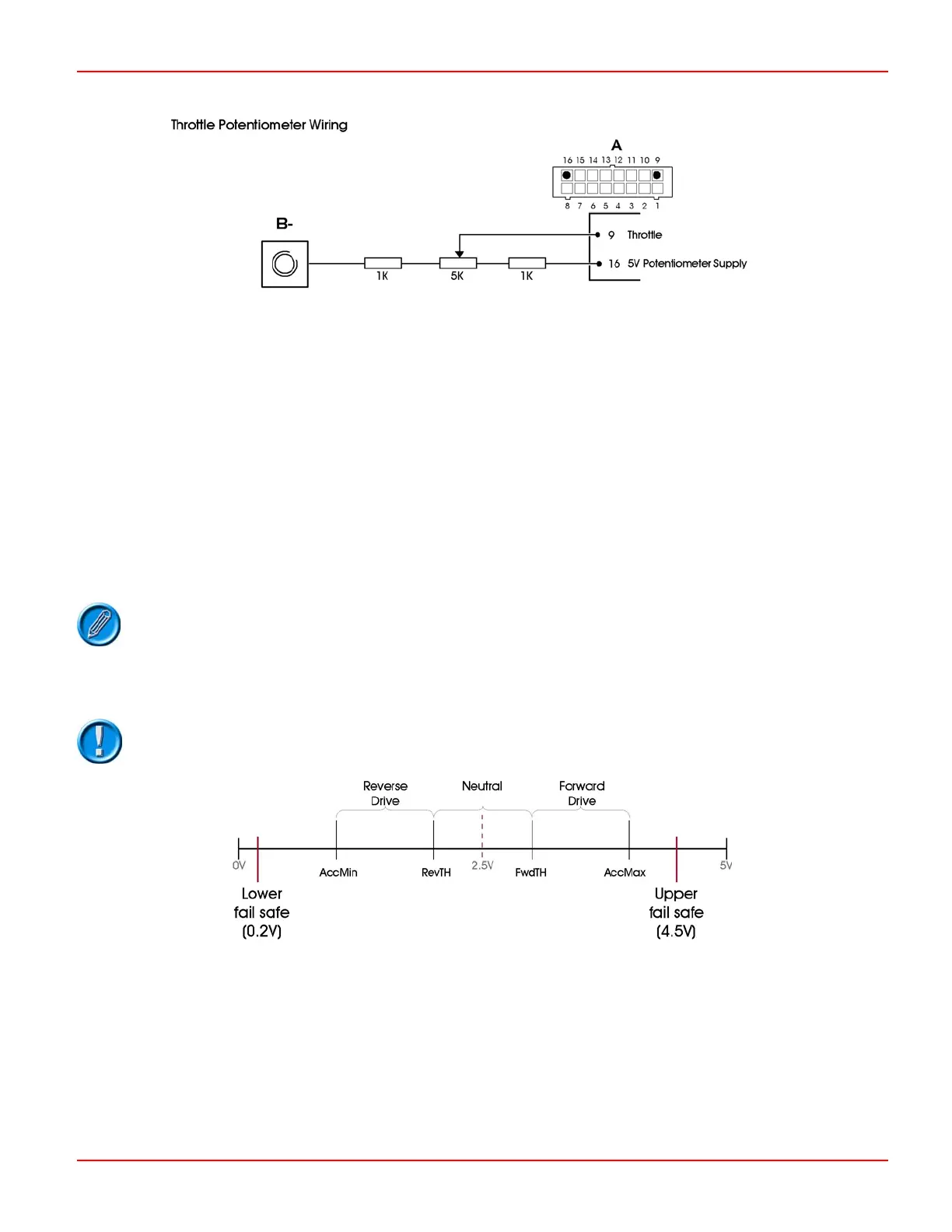
Since a wig-wag configuration does not include a separate switch wired to Connector A pin 3, 1kΩ series resistors should
be fitted as shown in the Throttle Potentiometer Wiring diagram to provide ‘wire-off’ protection.
You must only use a 5kΩ wig-wag potentiometer with the 1kΩ resistors.
Pin 10 – Keyswitch
This input should be connected to the switched side of the keyswitch. The other side of the keyswitch should be
connected to the battery positive supply.
A fuse of sufficient value to supply all contactor coil currents should be connected between the battery positive supply
and the keyswitch. The position of the fuse should be as close as possible to the tap-off point for the keyswitch supply.
SK79646-01 21
 Loading...
