PG DRIVES TECHNOLOGY AC TRACTION – SIGMAGAUGE
1 Introduction
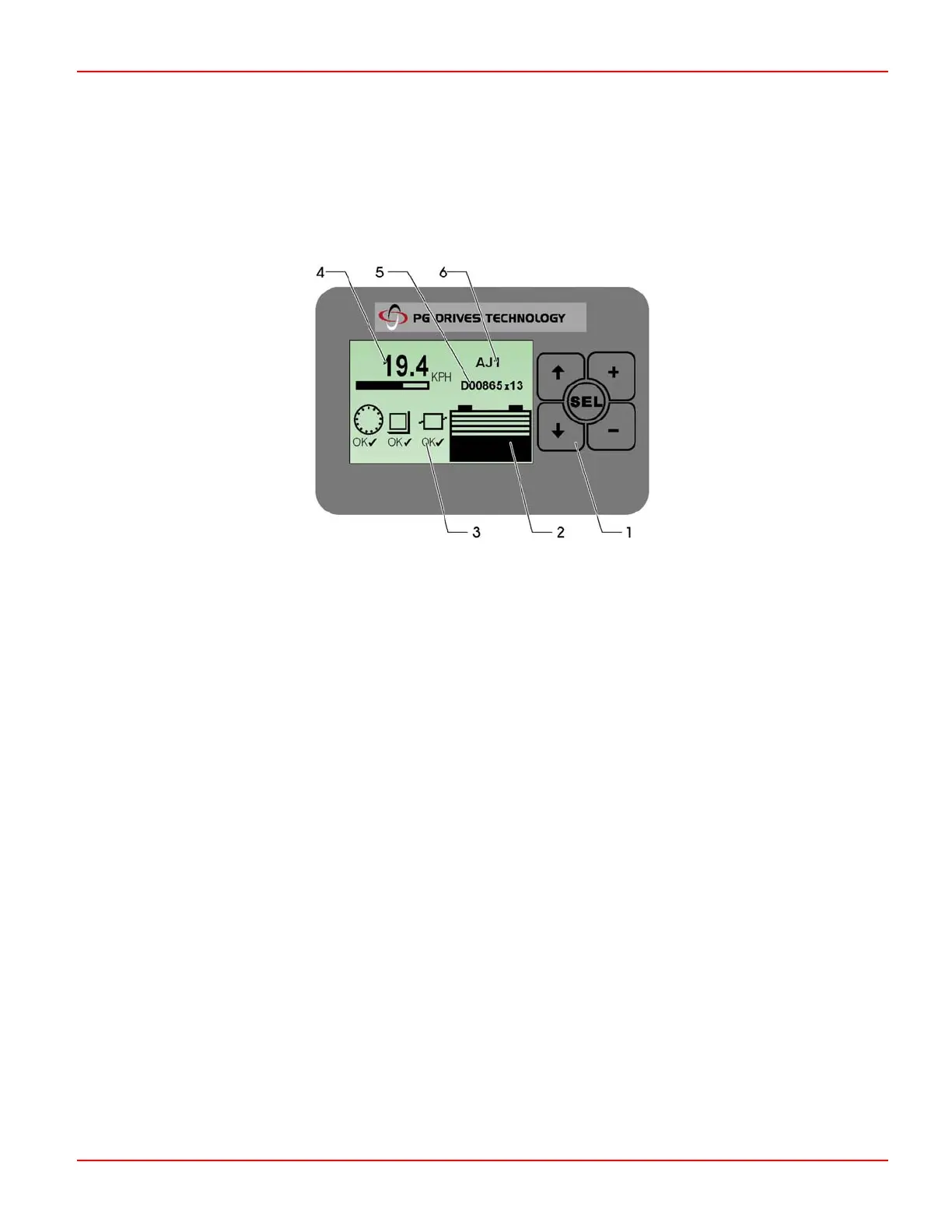
The Sigmagauge LCD is a highly versatile backlit, dot-matrix display, which presents vehicle status and diagnostic information to
the operator, using clear, easy-to-read icons.
1.1 General Information
1.1.1 Membrane Buttons
These are used for navigating and setting parameters in the Gauge Set-up menu.
1.1.2 Battery Discharge Indicator
Indicates the battery discharge state as set by CAN Node 0 (Master).
1.1.3 Fault Indication Field
Indicates the status of all Sigmadrive controllers in the system. A number is displayed within a ‘traction’, ‘pump’, ‘steering wheel’ or
‘CAN I/O’ icon to indicate which controller is experiencing a problem. When a fault is detected, the ‘OK’ symbol below the CAN
node indicator, is replaced with a fault icon (see Diagnostics chapter). The value of 3.10 Display Error Indication, determines
which failure types are displayed or ignored.
1.1.4 General Indication Field
The information shown in this area of the Sigmagauge is determined by the value set in 3.11 Display Status Field. Options are
none, accelerator demand, motor speed, vehicle speed, steering angle and motor current.
1.1.5 Hours Counter
Indicates either ‘work’ (drive) or ‘key’ hours & minutes, selectable in the Gauge Set-up menu. The hours counter value is stored in
the display. The controllers have their own separate counter.
1.1.6 Information Field
A 2x9 character field to show customized text, e.g. vehicle OEM and type. The membrane buttons can be used in the Gauge
Set-up menu to edit the text displayed.
SK79646-01 87
 Loading...
