P.O. Box 1306, Newport Beach, California 92663 • Phone: 714-751-0488 • Fax: 714-957-1621 • E-Mail: techservice@newmarpower.com
www.newmarpower.com
10
Therefore, the Phase Three charger is designed to utilize an
optional remote sensor (available from NEWMAR; model TCS-
12/24) which provides automatic temperature compensation. The
remote sensor will signal the charger to fine tune its output voltage
so that it is properly matched to the temperature of the battery/
battery environment. The adjustment rate is approximately -5 mV
per cell per °C. (Note: The temperature compensation option is
strongly recommended for sealed, valve-regulated, AGM or gel-
cell batteries.)
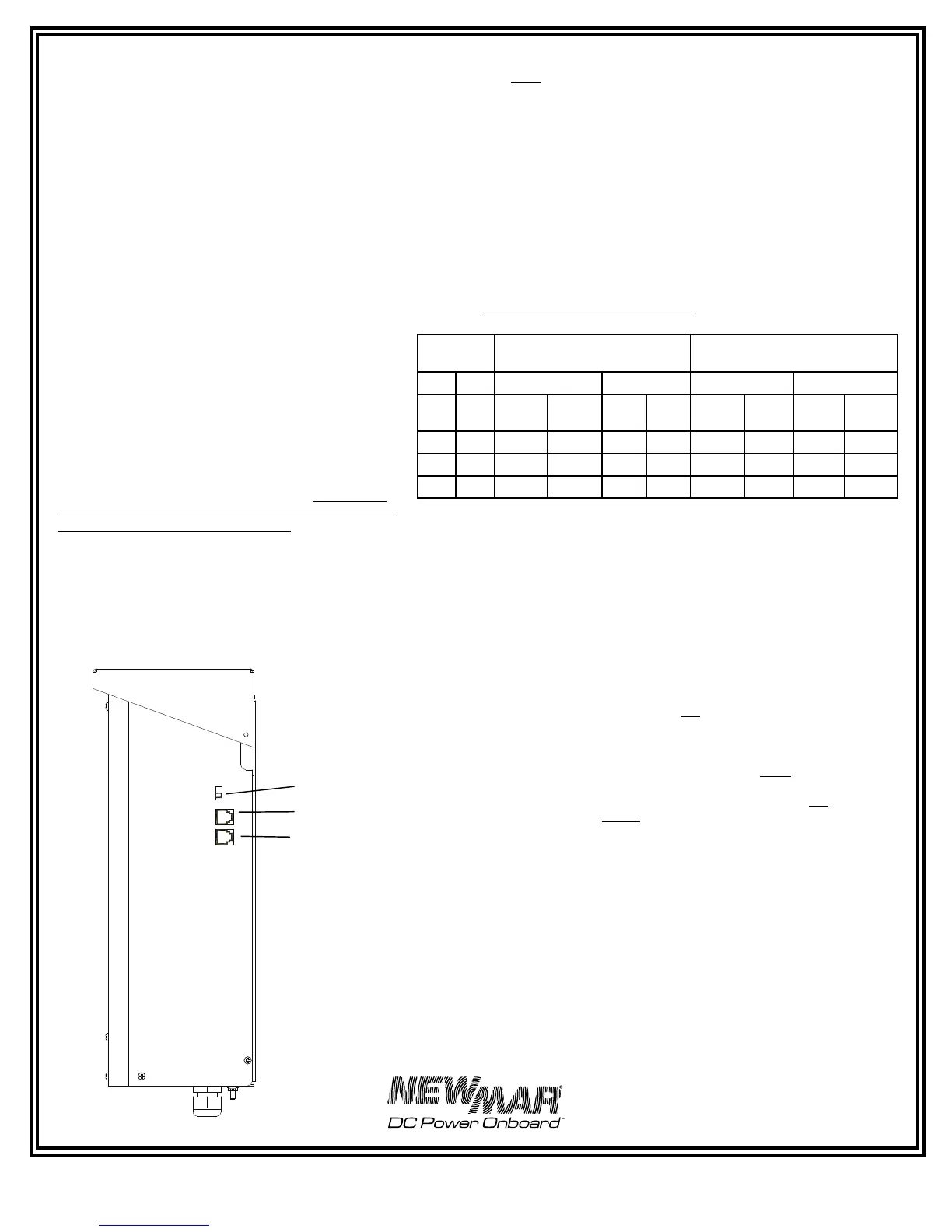
The remote sensor is provided with 30’ of cable. One end of the
cable is plugged into the temperature compensation jack which is
located on the right side of the charger (see FIGURE 6). The location
of temp sensor jack is identified on the front panel.
If additional cable length is required, additional cable is
commonly available from most electronics supply retailers such as
Radio Shack/Tandy. Request a 6 conductor modular-to-
modular line cord (part number 279-422, 25 feet long)
and 6 pin modular in-line non-reversing coupler (279-
423).
The sensor itself should be mounted on the inside of the
battery box, or more ideally, mounted onto one of the
batteries using a clamp or a small amount of silicon-
type adhesive. The sensor has a hole in the center which
will accommodate a # 6 screw. If you have access to
the exterior of a wall of the battery box, you may drill
a hole in the wall of the box and run the screw through
to mount the sensor onto the interior wall. Use caution
when drilling so that you do not accidentally puncture
the case of any battery inside the box.
Important note: When wiring multiple chargers in parallel (see
section III-E) and using the temperature compensation option,
you must use a separate sensor for each charger, and the sensors
must be mounted close together in the same battery box or on the
same battery for proper operation.
Without the temperature sensor installed the output of the charger
will be at the nominal voltages specified in the chart below at 72°
F (22.2° C). The absorption/float output voltage settings at that
temperature are listed in the chart.
To provide some examples which clarify the effect of the
temperature compensation sensor, the chart lists the absorption/
float output voltages of the charger when batteries are at 72° F (or
when the sensor is not installed), and at cold (50° F) or hot (90° F)
battery temperatures with the sensor installed:
Temperature Compensation Chart
* Factory pre-set voltages without temperature compensation
option installed
FIGURE 6: Temperature Compensation Sensor
and Remote Panel Installation
F) Equalize Timer Option
Some manufacturers of flooded lead-acid batteries recommend
a charging process known as equalization for extended battery
life. This process involves occasionally charging a wet lead-acid
battery at a very high voltage for a short period of time in order
to completely de-sulphate each of the battery plates, essentially
equalizing their voltage. The installer of the Phase Three charger
may choose to wire in this option at the time of installation.
Note: The equalization process is not recommended for sealed
valve regulated or gel-cell batteries.
The equalize circuit (connector located inside the PT charger)
should be wired through a manual or electric timer which
provides a closed contact when engaged and an open circuit
when timed out (SPST — Single Pole Single Throw). Do not use a
manually operated switch for activating the equalize circuit. This
is because unless the charger is reverted to a safe float voltage in
a timely manner, the batteries will almost certainly be damaged
or destroyed. The timer should be a 0-12 hour type, capable of
carrying a minimum of 100 mA at 5V D.C.
CAUTION: Do not install the timer in an area requiring ignition
protected equipment unless it has been certified to meet ignition
protection requirements.
The equalization circuit of the Phase Three charger boosts output
voltage to approximately 8 % above float voltage. Refer to the
battery manufacturer’s instructions when deciding the appropriate
time period setting for this voltage to achieve proper equalization,
while ensuring batteries are not damaged by increased battery
temperature. This installation should only be performed by a
qualified technician.
Battery
Temp.
Output V D.C: 12 Volt Models Output V D.C: 24 Volt Models
Charge Float Charge Float
° F ° C Gel-
Cell
Lead
Acid
Gel-
Cell
Lead
Acid
Gel-
Cell
Lead
Acid
Gel-
Cell
Lead-
Acid
50 10 14.4 14.6 14.0 13.8 28.8 29.2 28.0 27.6
72 22.2 14.0* 14.2* 13.6* 13.4* 28.0* 28.4* 27.2* 26.8*
90 32.2 13.7 13.9 13.3 13.1 27.4 27.8 26.6 26.2
 Loading...