P.O. Box 1306, Newport Beach, California 92663 • Phone: 714-751-0488 • Fax: 714-957-1621 • E-Mail: techservice@newmarpower.com
www.newmarpower.com
8
IV) OPERATION
A) Three Stage Charge Regimen
The Phase Three Battery Charger utilizes the three stage charge
regimen which is widely recommended by battery manufacturers
for allowing the fastest possible recharge time without loss of
batteries’ electrolyte (gel or liquid) which may be caused by
sustained charging at higher voltages.
This three stage regimen is initiated each time A.C. is first applied,
when drained batteries are most likely to be encountered, and
proceeds slowly or quickly through each stage depending on
the battery’s relative state of charge. (This also occurs when the
reinitialize button on the optional remote panel is activated; see
Remote Panel Option section for more information). Note: An
audible “clicking” noise from an internal relay may be heard when
the charger switches from one phase to another. This is normal
operation. The charge regimen proceeds as follows:
1) Bulk Phase: When batteries are significantly discharged the
charger responds initially by delivering a high amount of D.C.
current, at or near the charger’s maximum rated output, in order
to rapidly replenish them. It is during this stage that charging
current is maintained at a high level as battery voltage increases.
Bulk charging continues until battery voltage reaches the “charge”
voltage level (where batteries are at about 75-80% of capacity).
A current limit circuit prevents charger overload during this
maximum output stage.
Note: During this bulk phase the charger is in a “constant current”
mode; therefore, output current will stay constant while output
voltage decreases. Full output voltage is achieved and maintained
only when the charger switches to the absorption stage.
2) Absorption Phase: During this second stage of the charge cycle,
battery voltage is maintained at the “charge” voltage level. Output
current begins to taper off as the battery plates become saturated.
Charge voltage is maintained until the current sensing circuit
detects that output current has tapered to about 5-15 % of charger
rating*. At this point the batteries are at about 95 % of full charge
and the Phase Three charger switches to the third and final stage of
the charge cycle.
* Note: The absorption phase may also be ended by the time-out
circuit. See section IV-B, for a complete explanation of the purpose
and functioning of the time-out circuit.
3) Float Phase: For extended battery life the Phase Three then
automatically switches to a lower float voltage level. This float
charge keeps batteries at peak condition without overcharging.
The charger may be left in this stage for lengthy periods of time
without attention (though periodic checks of electrolyte level
in flooded batteries is recommended). It is not necessary or
recommended to shut the charger off when this stage is reached.
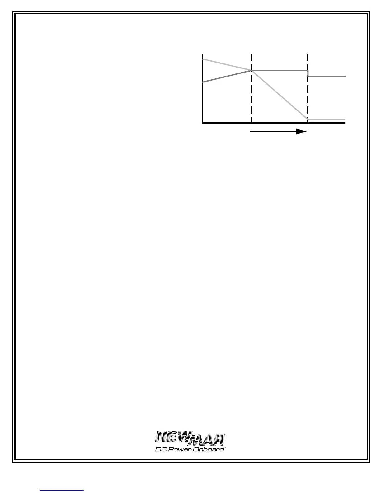
A typical three stage charging cycle is illustrated in FIGURE 4.
* Approximately 10 hours maximum at factory setting.
Note: If a load is applied during the absorption phase, the charger
may revert to the bulk phase depending on the total current draw.
When the charger times-out into the float phase, it will remain in
that phase regardless of current draw. The charger is still able to
deliver full output current when in the float phase. To re-initialize
the three stage process shut the charger off momentarily, then
back on again (or press the reinitialize button on the optional
remote panel)
B) Time-Out Circuit
Batteries have a tendency to lose their electrolyte and may be
damaged if they are maintained for long periods of time in the
elevated voltage of the absorption phase. Therefore, the Phase
Three Charger employs a special time-out circuit. This circuit is
initialized each time A.C. is first applied to the charger (or when the
reinitialize button on the optional remote panel is activated) and
runs for a pre-set interval before forcing the charger to go into the
float (lower voltage) mode. The functioning of the charger during
this interval is as follows:
If the current demand of the batteries/load falls below 5-15 % of
the charger’s output capacity prior to the circuit timing-out, the
charger will automatically switch to the float mode. If demand
rises to about 10-20 % of charger output capacity, it will return to
the elevated output voltage of the absorption phase. This switching
back and forth between modes may occur until the circuit times-
out (8-10 hours after A.C. is first applied), after which the charger
will remain at float voltage, until the circuit is re-initialized, either
by turning the charger off and then on again or by pressing the
re-initialize button on the optional remote panel.
Installation Note: The time-out circuit of the PT charger has
been set at about 8-10 hours, which is appropriate for battery
systems within the capacity range specified on the front panel of
the charger. If the charger is used with a battery system with a
capacity near (or outside) the upper or lower ranges of the specified
range of the charger, adjustment of the internally located time-out
circuit adjustment pot may be recommended. The procedure is as
follows:
FIGURE 4: Typical Charger Output Graph
(into battery without load)
BULK PHASE
ABSORPTION PHASE
FLOAT PHASE
AMP
S
AMPS
VOLTS
VO
LT
S
TIME
 Loading...