P.O. Box 1306, Newport Beach, California 92663 • Phone: 714-751-0488 • Fax: 714-957-1621 • E-Mail: techservice@newmarpower.com
www.newmarpower.com
6
E) Multiple Unit Parallel Wiring
If increased power or system redundancy is required, a second
charger may be wired in parallel. The unit is diode protected so
it will not be damaged by feedback from the second unit and
current limiting will prevent overloading in the case of a failure of
one of the units.
Observe the following guidelines when wiring a parallel unit.
1) Use only another identical charger model PT 80, PT-24-45U,
or PT-24-95U).. Do not use a different charger model, either
from NEWMAR or from another manufacturer.
2) Output wire length and gauge must be identical for each
charger to ensure proper load sharing.
3) Wire gauge for each charger must be the same used as if a
single charger were wired into the system by itself. Wire each
battery charger directly to the battery (Figure 1) or battery
switch (Figure 2) DO NOT daisy chain charger outputs.
F) A.C. Input Wiring
A.C. input is “universal” and operates in a range of 90-264 VAC,
47-63 Hz. No switch setting is required for either 115V A.C. or 230V
A.C. applications. Caution (230V applications only): If A.C. input is
derived from a source consisting of two HOT leads (phase-to-phase
230V A.C. input voltage) an external fuse or circuit breaker must
be used to protect the unfused (formerly NEUTRAL, now HOT) lead.
A.C. input for the charger must be routed through fuse or circuit
breaker on an A.C. distribution panel with proper safety/earth
chassis ground in accordance with all applicable local codes and
ordinances.
Recommended A.C. Input Wire Size:
115 VAC Input = 14 AWG minimum
230 VAC Input = 16 AWG minimum
Recommended Input Circuit Breaker:
115 VAC Input = 15 Amp
230 VAC Input = 10 Amp
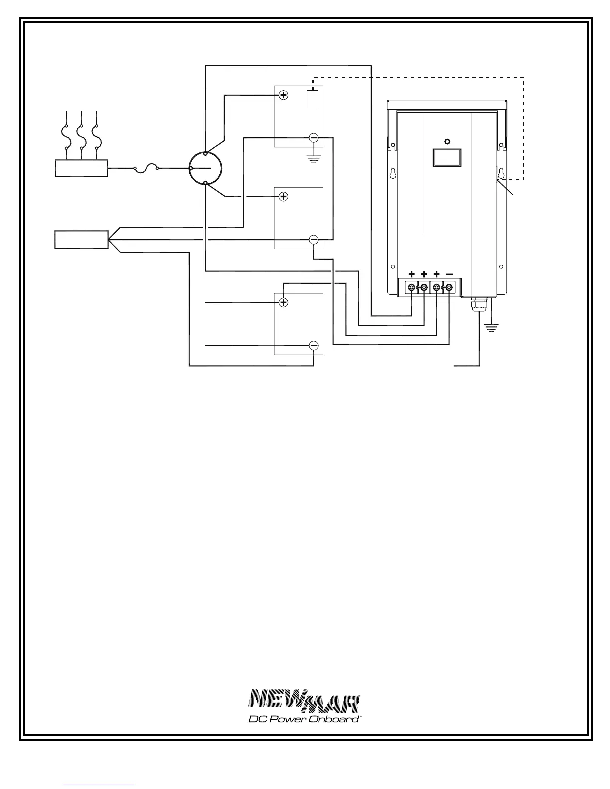
FIGURE 2: Wiring With Battery Switch
AC Input
*
Phase Three
Battery
Charger
Home
Bank 1
Master
Battery
Switch
+ Bus
– Bus
Home
Bank 2
Gen Bank
B
A
T
T
1
B
A
T
T
2
B
A
T
T
3
C
O
M
M
O
N
T
C
S
* Per ABYC A-31: A D.C. chassis
grounding conductor shall be
connected from the case of the
battery charger to the engine
negative terminal or its bus, and must
not be more than one size under that
required for the D.C. current carrying
conductor and not less than 16 AWG
Note: This diagram does not illustrate a complete system. Refer to ABYC standards E-11 AC
& DC electrical system on boats
Important: Install fuses at batteries per ABYC recommendations.
Optional
Temperature
Compensation
Sensor See
page 9 for
installation
information.
Use provided
cable clamps
to secure
probe cable
Note: PT 80/PT-24-
45U illustrated, same
configuration applies to
PT-24-95U.
 Loading...