P.O. Box 1306, Newport Beach, California 92663 • Phone: 714-751-0488 • Fax: 714-957-1621 • E-Mail: techservice@newmarpower.com
www.newmarpower.com
5
*Per ABYC A-31: A D.C. chassis grounding conductor shall be
connected from the case of the battery charger to the engine
negative terminal or its bus, and must not be more than one size
under that required for the D.C. current-carrying conductors, and
not less than 16 AWG.
Make a mark on the wall or bulkhead where each of the
keyhole slots will be located. Then drive a screw about halfway
in at each of these marks. Hang the charger onto the bulkhead
using the keyhole slots. Doing this will save you from having to
support the charger’s weight while you are driving in the four
permanent mounting screws. Note: The keyhole slots may be
used for additional support screws but they are not to be used as
permanent mounting points by themselves.
IMPORTANT: Although the charger is constructed of materials
and in a manner which makes it highly resistive to the corrosive
effects of moisture in the environment, the charger is not water-
resistant. Do not mount the charger where there is a possibility of
water entering the unit. Evidence of water entry into the charger
will void the warranty.
D) D.C. Output Wiring
Note: Only qualified service personnel should access the output
terminals of the charger.
Whether working with existing battery charger output wires or
installing new ones, make sure the battery(s) is disconnected
from these wires before connecting them to the charger’s output
terminals.
For secure installation D.C. output wires must be attached with ¼”
crimp ring lug terminals sized appropriately to fit wire gauges as
listed below.
The D.C. wire size table below may be used to determine the
correct gauge wire based on the model you have and the length
of wire run from the charger to the batteries. Once the output
wiring has been attached to the chargers output posts, install the
clear plastic terminal cover provided with the charger
Model Length of Wire from Charger to Batteries (in feet)
10’ 15’ 20’
Minimum Wire Gauge AWG (mm)
PT 80 #2 (35mm) #1 (50mm) #1/0 (70mm)
PT-24-45U #6 (16mm) #6 (16mm) #4 (25mm)
PT-24-95U #2 (35 mm) #2 (35 mm) #2 (35 mm)
*Based on N.E.C. Minimum Wire Size Chart and ABYC 3% Voltage
Drop Chart
ENSURE THAT LEADS ARE PROPERLY FUSED AT THE BATTERY.
(REFER TO ABYC RECOMMENDATIONS.)
A note about the internal D.C. fuse: The internal wiring of the
Phase Three charger is protected against dangerous overheating
in the event of an internal short, or reverse polarity hook-up, by an
internal d.c. fuse. The fuse is not user replaceable. If this fuse blows
the unit must be returned to NEWMAR or a qualified electronic
technician for repair.
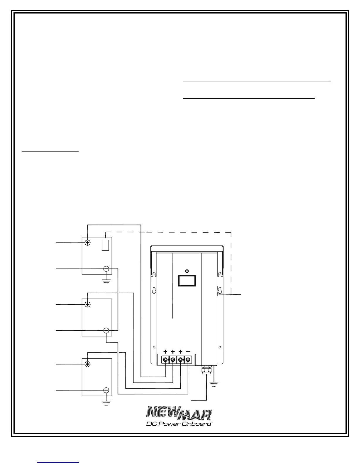
Typical D.C. wiring configurations are illustrated in FIGURES
1 and 2.
FIGURE 1: Simple D.C. Wiring (Preferred Method)
Phase
Thre
e
Battery
Charter
T
C
S
AC Input
House
Bank 1
House
Bank 2
Gen
Bank
B
A
T
T
1
B
A
T
T
2
B
A
T
T
3
C
O
M
M
O
N
*
* Per ABYC A-31: A D.C. chassis grounding
conductor shall be connected from the case
of the battery charger to the engine negative
terminal or its bus, and must not be more
than one size under that required for the D.C.
current carrying conductor and not less than
16 AWG
Note: This diagram does not illustrate a
complete system. Refer to ABYC standards
E-11 AC & DC electrical system on boats
Important: Install fuses at batteries per ABYC
recommendations.
Optional Temperature
Compensation Sensor See page
9 for installation information. Use
provided cable clamps to secure
probe cable
Note: PT 80/PT-24-45U
illustrated, same configuration
applies to PT-24-95U.
 Loading...