P.O. Box 1306, Newport Beach, California 92663 • Phone: 714-751-0488 • Fax: 714-957-1621 • E-Mail: techservice@newmarpower.com
www.newmarpower.com
12
in-line (if, for instance, the battery must be removed for any
purpose and A.C. is still available). All but the most sensitive D.C.
powered electronic devices will function as normally as if powered
by a battery. In addition, the current limiting circuitry enables
the charger to handle the high start-up surges associated with
inductive loads, such as D.C. motors in radar sets.
VI) SPECIFICATIONS
Input Voltage/Frequency: 90-264V A.C.; 47-63 Hz
Power Factor: .95 @ 230V A.C., .98 @ 115V A.C.
Input Current @ Full Load:
PT 80 & PT-24-45U: 7 amps @ 230V A.C.; 12 amps @ 115V A.C.
PT-24-95U: 14 amps @ 230V A.C.; 26 amps @ 115V A.C.
Output Current @ 115/230V A.C. Input:
PT 80: 80 amps maximum in Bulk / Absorption / Float Phases
PT-24-45U: 45 amps maximum in Bulk / Absorption / Float Phases
PT-24-95U: 95 amps maximum in Bulk / Absorption/ Float Phases
Nominal Output Voltages (without Temperature Compensation
option installed or at 22.2 °C with Temperature Compensation
option installed):
Temperature Compensation (with Sensor Installed):
- 5 mV per cell per ° C
Temperature Rating: -10° C to +60° C; Derate linearly from 100 % @
50° C to 80 % @ 60° C
Recommended Battery Type/Capacity: Gell-Cel, Flooded or
Sealed Lead-Acid;
PT 80 : 6 cell, 140-700 Amp-Hour
PT-24-45U: 12 Cell, 80-400 Amp-Hour
PT-24-95U: 12 Cell, 180-950 Amp-Hour
Protection Features: Input Fuse, Output Fuse, Current Limiting,
Over Voltage Protection, Cooling Fans, Automatic Thermal
Shutdown/Recovery
Case Size: PT 80 & PT-24-45U
14.8” H* x 9.6” W x 5.6” D*
37.6 cm* x 24.4 cm x 14.2 cm*
*Add 1” (2.54 cm) to height and .5” (1.27 cm) to depth
when installing optional drip shield.
Weight: 15.2 lbs. (6.9 kg.)
Case Size: PT-24-95U
17.5” H* x 12.0” W x 7.2” D*
44.5 cm* x 30.5 cm x 18.3 cm*
*Add 2” (5.08 cm) to height and 1” (2.54 cm) to depth
with drip shield installed.
Weight: 24.5 lbs. (11.1 Kg.)
Compliance: Carries the CE Mark
VII TROUBLESHOOTING
Note: The PT 80, PT-24-45U, and PT-=24-95U chargers incorporate a self-contained A.C. to D.C. conversion module which utilizes
numerous automatic protection circuits. The A.C. input and D.C. output fuses which protect internal wiring are housed inside the charger
module. Under most circumstances these fuses will fail only if the charger has an internal fault. Hence, they are not intended to be
user-replaceable and any condition which has caused a blown fuse will likely require repair of other internal circuitry by a qualified
technician. If an apparent charger fault cannot be corrected using any of the recommendations in this section, the charger should be
returned to the factory or place of purchase for inspection and repair or replacement.
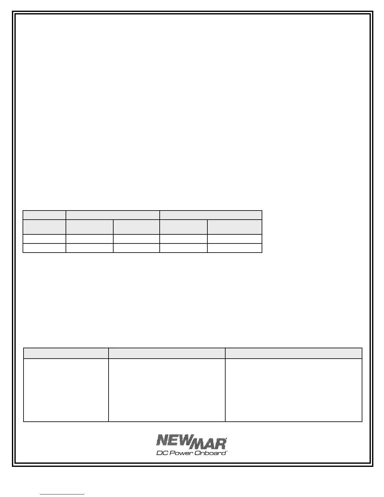
PT 80 PT-24-45U & PT-24-95U
Setting Charge
@ 50% load
Float
@ .5 amp load
Charge
@ 50% load
Float
@ .5 amp load
Gel-Cell 14.0V D.C. 13.6V D.C. 28.0V D.C. 27.2V D.C.
Flooded/AGM 14.2V D.C. 13.4V D.C. 28.4V D.C. 26.8V D.C.
Problem Possible Cause Solution
A. Batteries not coming up to full
charge
1. Extremely discharged batteries requiring
long recharge time
2. Charger limiting its output due to overload
or over-temperature conditions
3. Fan not operating properly, causing
charger to over-heat, reducing or ceasing
power output
1. Turn off all D.C. loads and allow charger 24-48
hours to recharge batteries
2. Reduce D.C. load and/or determine cause of over-
temperature condition (see section III-B, Location)
3. Check to ensure there is no blockage at fan intake
on bottom of charger. Replace fan if necesssary (see
section IV-G, Cooling Fan)
 Loading...