P.O. Box 1306, Newport Beach, California 92663 • Phone: 714-751-0488 • Fax: 714-957-1621 • E-Mail: techservice@newmarpower.com
www.newmarpower.com
9
(Caution: Ensure A.C. input has been disconnected before
proceeding)
1) Remove the three screws on the front panel and seven screws
on the sides of the unit.
2) Remove the main cover from the charger base, taking care
not to bend the two jacks on the right side of the charger out
of position. Locate the potentiometer labeled “TIMER ADJ” on
the small charger function circuit board on the right side of the
charger.
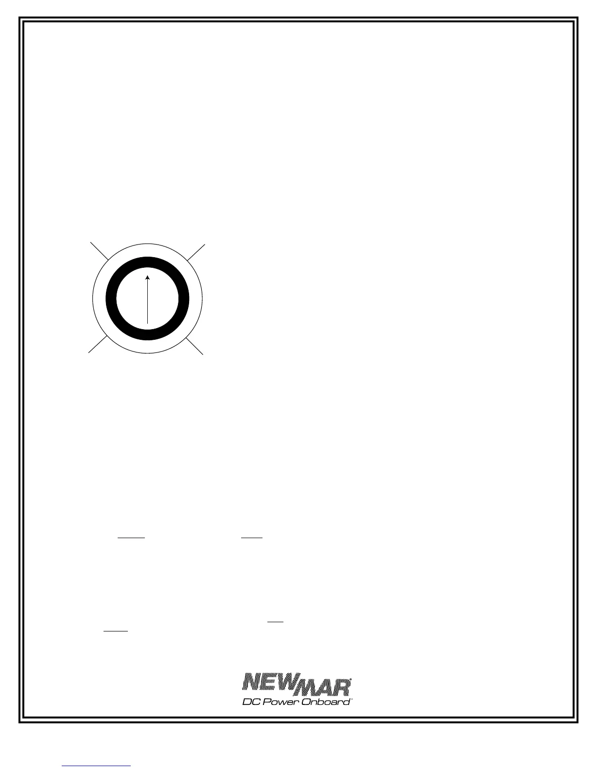
3) Using a small flat tip screwdriver, turn the potentiometer
clockwise to increase the amount of time the charger remains
in the absorption mode before timing out, or counterclockwise
to decrease the amount of time. The approximate ranges are
illustrated below.
Note: Once the time-out circuit has put the charger into float
mode, the charger will remain in this mode. Since the Phase
Three Charger is well regulated, it is able to deliver its full rated
output current in this mode and battery discharge will not occur
(provided load current does not exceed charger rating and output
wiring is properly sized).
4) Reinstall the charger cover
C) Gel-Cell — Flooded/AGM Switch
According to most battery manufacturers, the ideal charge
regimen for gel-cell and flooded (wet) lead-acid or AGM (Absorbed
Glass Mat) batteries differs somewhat.
The gelled electrolyte in a sealed battery may be lost or damaged
by high voltage and, once lost, cannot be replaced as it can
with a wet lead acid battery. Manufacturers of gel-cells usually
recommend an ideal charge voltage which is slightly lower
for a gel-cell than a lead-acid battery. (The charge regimen
recommended for AGM batteries is typically similar to that of
flooded lead-acid batteries.)
However, when the charger is in the float voltage mode over
lengthier periods of time, gelled electrolyte in a sealed battery
is not susceptible to evaporation, as is the non-immobilized
electrolyte of a wet lead acid battery. This evaporation can be
accelerated by the applied voltage. Consequently, the ideal float
voltage is slightly higher for a gel-cell than a lead-acid or AGM
battery.
The ideal charge/float regimen has been programmed into the
Phase Three Charger for either sealed gel-cell or flooded lead-acid/
AGM batteries. Simply make the proper selection for your battery
type via the slide switch on the right side of the charger. The switch
positions are indicated on the Charger’s left side panel (see Figure
6) l. Use a ball point pen or similar object to slide it into the correct
position.
Note: A wide variety of batteries are now available which do not
conform to conventional descriptions as “gel-cell” or “lead-acid”.
You are advised to consult the manufacturer of your particular
battery as to proper charging regimen, and use the battery
type selection switch setting which most closely conforms to the
recommended voltages.
See the SPECIFICATIONS section for the actual preset charge and
float voltages for the PT-80 and PT 80, PT-24-45U, and PT-24-95U.
D) Remote Monitor Panel Option
A Remote Monitor Panel is available from NEWMAR (model RP)
which will enable you to monitor the charger’s status at-a-glance
from a remote location. Red and green L.E.D.’s indicate whether
the charger is in the bulk, absorption or float phase of the charge
cycle. In addition, the panel features a re-initialize button, which,
when pressed, will cause the charger to restart the three phase
cycle. This resets the time-out circuit (see section B, above) Time-
out Circuit, above). Note: The charger may not stay in the bulk or
absorption mode after pressing the re-initialize button. If batteries
are at or near full charge, the charger will quickly revert to the
float mode.
The panel comes pre-wired with 30’ of cable and 4 mounting
screws. Simply install the panel at the desired location and insert
the plug on the end of the cable into the remote panel jack which
is located on the right side of the charger. (See Figure 10.) The
remote panel jack is identified on the front panel.
Note: Inadvertently putting the remote panel plug into the temp
compensation jack (or vice versa) will not harm the charger. If the
panel does not appear to function correctly, check to see that it is
plugged into the correct jack.
If additional cable length is required, additional cable is commonly
available from most electronics supply retailers such as Radio
Shack/Tandy. Request a 6 conductor modular-to-modular line cord
(part number 279-422, 25 feet long) and 6 pin modular in-line non-
reversing coupler (279-423).
E) Temperature Compensation Option
Because low battery temperature increases resistance to charging
and high battery temperature reduces impedance, requiring
a lower charge voltage, the ideal charging voltage will vary
depending on the temperature of the battery’s environment when
it is being charged.
If a charger has a fixed output voltage which is ideal at, say 72° F,
that same output may cause a battery charged in a consistently
high temperature environment to be overcharged, resulting
in excessive loss of electrolyte. Conversely, if the batteries are
in a consistently cool environment, they may be chronically
undercharged, resulting in sulfation of the battery plates. Either of
these two conditions will shorten battery life.
FIGURE 5: Adjusting the Time-out Circuit
 Loading...