P.O. Box 1306, Newport Beach, California 92663 • Phone: 714-751-0488 • Fax: 714-957-1621 • E-Mail: techservice@newmarpower.com
www.newmarpower.com
7
(In marine applications) All charger wiring should be installed in
accordance with UL, U.S. Coast Guard and/or A.B.Y.C. regulations
and recommendations, as well as all relevant local codes. See
REFERENCE APPENDIX at the end of this manual for sources.
A note about the A.C. input fuse: The A.C. input of your charger
is protected by an input fuse which is located inside the unit.
Due to the current limiting characteristic of the charger, it is
highly unlikely that this fuse will blow unless there is some other
malfunction within the charger. This fuse is not user-replaceable.
Replacement of the input fuse must be performed by a qualified
service person.
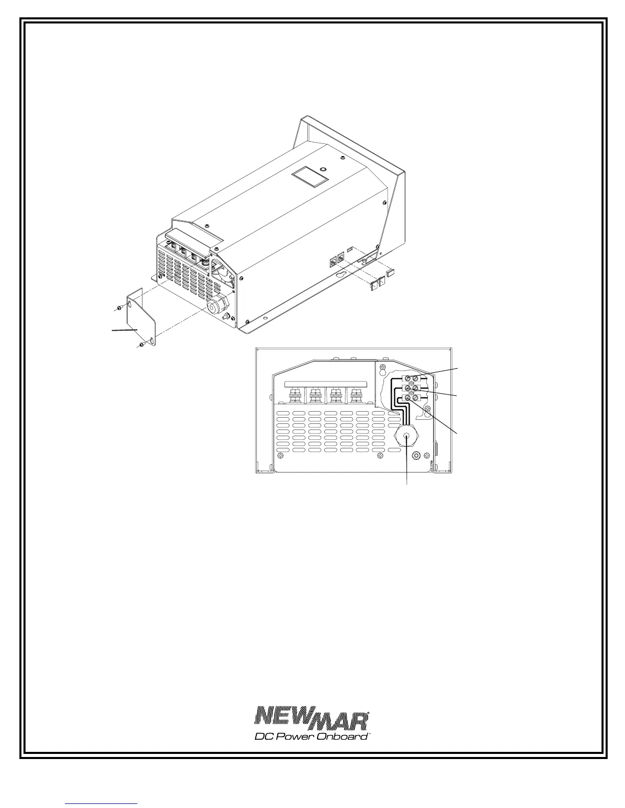
FIGURE 3: AC Input Wiring
Input Wiring
Acess Plate
Hot (All Systems) ‘L1’
Neutral (Euro 230V)or
Hot(USA 230V) “L2/N”
Earth Ground Safety
AC Input Cable Strain
Relief Clamping Range: .2” - .47”
Note: PT 80/PT-24-45U illustrated,
same wiring configuration
applies to PT-24-95U, but access
plate is on left side.
Note: access plate on left
side on PT-24-95U.
 Loading...