EasyManuals Logo

Phase Technology Phase Perfect PT007 User Manual

Phase Technology Phase Perfect PT007
48 pages
To Next Page IconTo Next Page
To Previous Page IconTo Previous Page
Page #7 background imageLoading...
Page #7 background image
1 | Page
V2.1
THEORY OF OPERATION
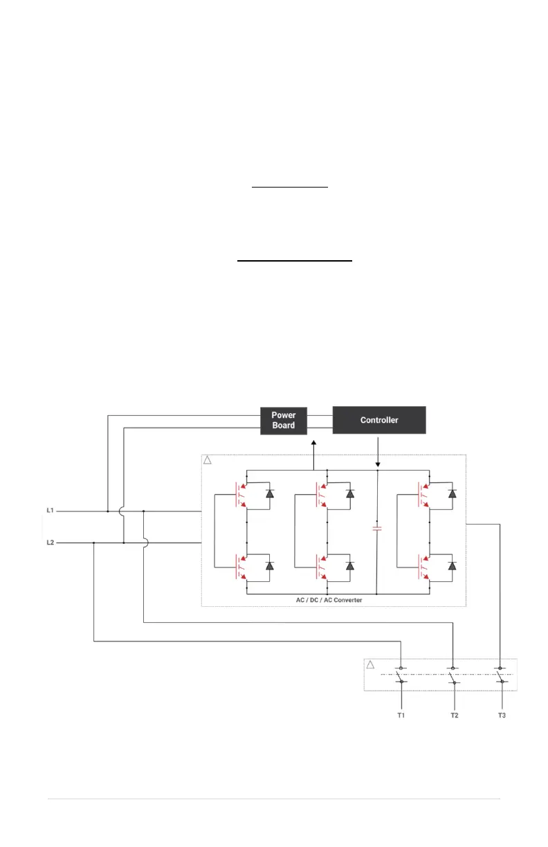
L1 and L2 of the single-phase input pass directly through the phase converter to provide
two legs of the three-phase output. The input module charges a DC bus from the input
lines. The output module uses power from the DC bus to generate the third leg of the three-
phase output. The third leg is generated to limit voltage imbalance between the three legs
to ≤ 2%. Voltage imbalance is calculated according to the NEMA MG1 standard.

 

Where:






󰇛






󰇜
Block Diagram
The diagram in Figure 1 illustrates the basic design schematic of the Phase Perfect Digital
Phase Converter.
Figure 1 Phase Perfect Digital Phase Converter Schematic

Questions and Answers:

Question and Answer IconNeed help?

Do you have a question about the Phase Technology Phase Perfect PT007 and is the answer not in the manual?

Phase Technology Phase Perfect PT007 Specifications

General IconGeneral
BrandPhase Technology
ModelPhase Perfect PT007
CategoryMedia Converter
LanguageEnglish