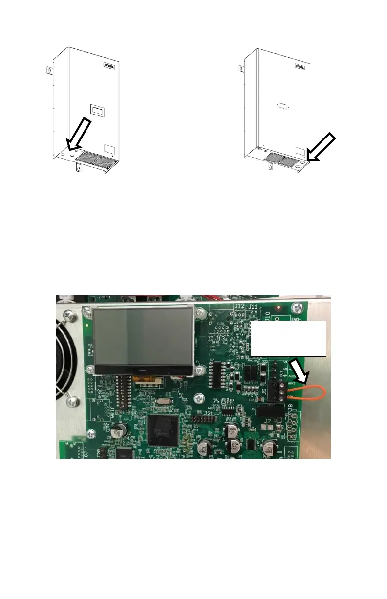
Figure 18 – PTE Conduit Locations:
PTE007, PTE007QT, PTE010, PTE010QT,
PTE407, PTE407QT PTE410, PTE415QT,
PTE420QT
Figure 19 – PTE Conduit Locations:
PTE015, PTE020, PTE207, PTE210,
PTE215, PTE220
ON/OFF Control Wiring
The output of the converter can be controlled with a switch connected between the AUX1
or AUX2 and COM terminals. If installed, remove the factory installed jumper wire and
replace with a switch. Jumper wire can be seen in Figure 20 below.
Figure 20 – Control Terminal Locations
When AUX1 to COM or AUX2 to COM is closed, the output is energized after a delay of
approximately two seconds. When AUX1 and AUX2 to COM are open, the output of the
converter will be de-energized. The diagram in Figure 21 illustrates the UL508A panel
shop and customer installed options including an ON/OFF control switch.