EasyManua.ls Logo

Philips 32” LCD TV User Manual

Philips 32” LCD TV
59 pages
To Next Page IconTo Next Page
Page #1 background imageLoading...
Page #1 background image
Service Manual
Contents
32PFL4909/F7 PHILIPS (Serial No.: ME1)
32PFL4609/F7 PHILIPS (Serial No.: ME1)
32PFL4909/F8 PHILIPS (Serial No.: XA1)
32” LCD TV
chassis PL14.12
140324
© 2014 Funai Electric Co., Ltd.
All rights reserved. No part of this manual may be reproduced, copied, transmitted, disseminated, transcribed,
downloaded or stored in any storage medium, in any form or for any purpose without the express prior written
consent of Funai. Furthermore, any unauthorized commercial distribution of this manual or any revision hereto
is strictly prohibited.
Information in this document is subject to change without notice. Funai reserves the right to change the content
herein without the obligation to notify any person or organization of such changes.
with the design is a registered trademark of Funai Electric Co., Ltd and may not be used in any way
without the express written consent of Funai. All other trademarks used herein remain the exclusive property of
their respective owners. Nothing contained in this manual should be construed as granting, by implication or
otherwise, any license or right to use any of the trademarks displayed herein. Misuse of any trademarks or any
other content in this manual is strictly prohibited. Funai shall aggressively enforce its intellectual property rights
to the fullest extent of the law.
This service manual contains information of different types of models.
Make sure to refer to the section describing your model.
Question and Answer IconNeed help?

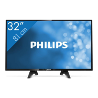
Do you have a question about the Philips 32” LCD TV and is the answer not in the manual?

Philips 32” LCD TV Specifications

General IconGeneral
Screen Size32 inches
Display TechnologyLCD
Aspect Ratio16:9
Refresh Rate60 Hz
Built-in SpeakersYes
HDMI Ports2
USB Ports1
Speaker Output10 W
Energy Efficiency ClassA
Resolution1366 x 768 pixels

Summary

Important Safety Notice

Important Safety Precautions

Safety Check after Servicing

Clearance Distance

Confirms specified clearance distance between soldered terminals and surrounding metallic parts.

Leakage Current Test

Confirms specified leakage current between earth ground and exposed accessible parts.

Standard Notes for Servicing

How to Remove / Install Flat Pack-IC

Procedure for removing and installing flat pack ICs using a hot-air desoldering machine.

Instructions for Handling Semi-conductors

Ground for Human Body

Ensures proper grounding for technicians to remove static electricity from the body.

Ground for Workbench

Ensures proper grounding for the workbench to prevent static discharge to semiconductors.

Cabinet Disassembly Instructions

Disassembly Flowchart

Visual flowchart showing the sequence for cabinet disassembly and reassembly.

Disassembly Method

Detailed steps for disassembling cabinet parts and accessing internal components.

Electrical Adjustment Instructions

Purity Check Mode

Checks for non-active pixels using full-screen red, green, blue, and white displays.

VCOM Adjustment

White Balance Adjustment

How to Initialize the LCD TV

Firmware Renewal Mode

Troubleshooting

[Video Signal Section]

Troubleshooting flowcharts for issues related to video signal processing and display.

[Audio Signal Section]

Troubleshooting flowcharts for problems with audio output and signal processing.

Block Diagrams

System Control Block Diagram

Block diagram illustrating the system control functions and interconnections of major units.

Video/Audio Block Diagram

Block diagram showing the video and audio signal paths and processing units.

Digital Signal Process Block Diagram

Block diagram detailing the digital signal processing stages and components.

LED Backlight Drive Block Diagram

Block diagram illustrating the LED backlight drive circuitry and its control.

Power Supply Block Diagram

Block diagram of the power supply unit, showing its internal circuits and connections.

Schematic Diagrams / CBA and Test Points

Power Supply Schematic Diagram

Digital Main 1 Schematic Diagram

Function Schematic Diagram

IR Sensor Schematic Diagram

Wiring Diagram

Exploded Views

Packing

Revision History

Comparison List of Model Names

Related product manuals