9-1
Cabinet Disassembly Instructions
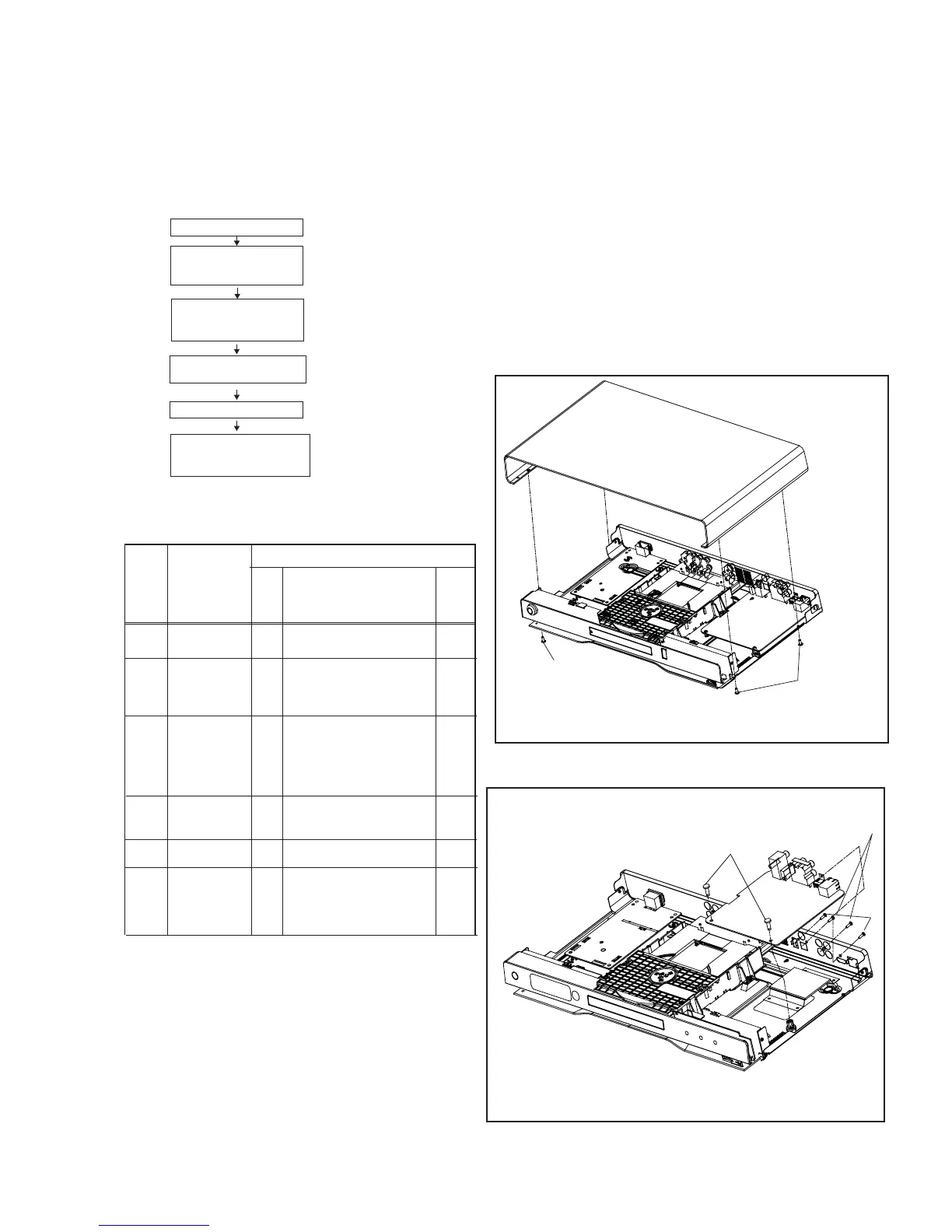
1. Disassembly Flowchart
This flowchart indicates the disassembly steps to gain
access to item(s) to be serviced. When reassembling,
follow the steps in reverse order. Bend, route, and
dress the cables as they were originally.
2. Disassembly Method
Note:
(1) Identification (location) No. of parts in the figures
(2) Name of the part
(3) Figure Number for reference
(4) Identification of parts to be removed, unhooked,
unlocked, released, unplugged, unclamped, or
desoldered.
Axx = Screw, CNxx/Jxx/CONxx = Connector
D3.5X12BA is specification of screw.
* = Unhook, Unlock, Release, Unplug, or Desolder
e.g. 7(A01) = seven Screws
ID/
Loc.
No.
Part
Removal
Fig.
No.
Remove/*Unhook/
Unlock/Release/
Unplug/Desolder
Note
[3] DVD Loader Driver,
Optical Socket Board,
Radio Transmit Board
DVD Loader
Driver,
Optical Socket
Board,
Radio Transmit
Board
[4] L/R Speaker,
Door U/D Control Board
L/R Speaker,
Door U/D Control
Board
[5] DVD Door
DVD Door
[6] Display Board,
Door L/R Control Board,
Touch Buttom Board
Display Board,
Door L/R Control
Board,
Touch Buttom
Board
[2] Decoder Board
Decoder Board
[1] TOP Cover
[1]
[2]
[3]
[4]
[5]
[6]
TOP Cover
4(A01) D3x6KMTT,
4(A02) D3x6BM,
2(A03) D3x10PA
12(A03) D3x10BA,
1(A08) D2x3FB
1(A06) D2.6x6BB
5(A02) D2x3FB,
2(A05) D3x8PA,
2(A05) D2.6x6BB
2(A04) D3x10FA,
2(A06) D2.6x6BB,
4(A10) D2.6x10PWT
D1
D2
D3
D4
D5
D7
D6
Fig. D1
Fig. D2
A01
A02
A02
A03
A01