Mechanical Instructions
EN 10 BP2.2U, BP2.3U4.
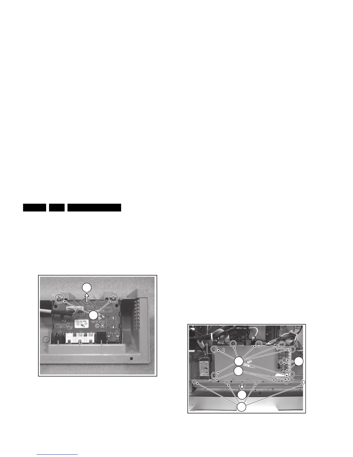
4.3.6 Side I/O Panel
After removal of the Speaker Compartment Covers, this panel
is accessible.
1. Disconnect the cable(s) from the panel.
2. Remove the T10 mounting screws [1] that hold the assy.
3. Take out the panel from its bracket [2].
When defective, replace the whole unit.
Figure 4-7 Side I/O panel removal
4.3.7 Multimedia Card Reader (if present)
After removal of the Speaker Compartment Covers, this panel
is accessible.
1. Unplug the related USB cable at the top of the SSB.
2. Remove the two T10 mounting screws [1] that hold the
assy.
When defective, replace the whole unit.
Figure 4-8 Multimedia card reader removal
4.3.8 Audio Amplifier Panel
1. Disconnect all cables from the Audio Amplifier panel.
2. Remove the T10 mounting screw from the Audio panel.
3. Release the two plastic fixation pins.
4. Take out the Audio panel (it hinges at the top side).
4.3.9 LED Panel
1. Disconnect the cable(s) from the panel.
2. Remove the T10 mounting screws that hold the panel.
3. Take out the panel.
When defective, replace the whole unit.
4.3.10 Small Signal Board (SSB)
1. Remove all connector fixation screws [1] at the connector
plate (bottom side), and at the shielding plate (rear side).
2. Remove the fixation screws [2] of the connector plate itself.
3. Remove all shielding fixing screws [3].
4. Slide the connector plate away from the SSB [4], and lift the
shielding from the SSB.
5. Unplug all cables on the SSB.
6. Remove the mounting screws that hold the SSB, and lift
the panel from the set.
Figure 4-9 SSB top shielding
F_15400_116.eps
190505
1
2
F_15400_118.ep