SERVICE MANUAL
LBB 3310/00, 3330/00 and 3331/00 page: 17 Date of issue:
4822 861 11006 July 1998
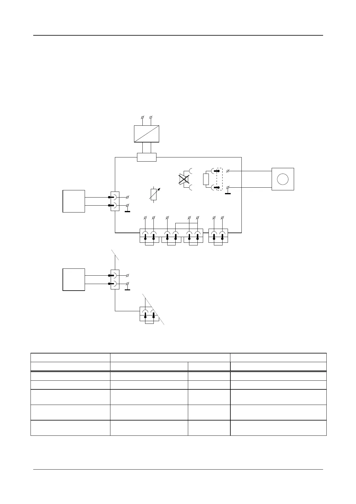
Nominal level, maximum level and bandwidth
Connect successively a sine-wave generator to the left and right external microphone input connections, (“MIC-IN+”
(M131) and “MIC-IN-” (M132) ) related to GND (M133) according to figure 5.
NOTE: be sure that the gain control potentiometer (R140) of the external microphone input is set to the middle
position.
629548 27
25Ω
X205
M119
X150X110
X10
AC
24V DC
Power Supply
90 ... 264V AC
~~
Loudspeaker
PCB CPSU
M110 M111 M121 M122 M124 M150 M151
M2
(GND) (GND) (GND)
X130
R140
X130
Ext. mic
Input
Ext. mic
Input
G1
G1
M133
M133
M131
M132
1
1
GND
GND
2
3
mic-IN+
mic-IN-
+
-
A1
V
003_005.cdr
LR IN
Rec-INLine-IN Rec-IN Telephone
Sine-Wave
Generator
Sine-Wave
Generator
+
+
-
-
69
X110
M110 M111 M1
(GND)
RLine-IN
Figure 5
settings for G1 measurement results for A1
Amplitude Frequency Amplification
Nominal level -56 dBV (1.6 mVrms) 1 kHz -15 dBV +/- 2dB (85dB SPL)
Maximum level -31 dBV (28.2 mVrms) 1 kHz +10 dBV +/- 2 dB (110 dB SPL)
Bandwidth -56 dBV (1.6 mVrms) 125 Hz -3dB +/- 2dB related to nom. level at
1kHz
Bandwidth -56 dBV (1.6 mVrms) 12.5 kHz -1dB +/- 1dB related to nom. level at
1kHz.
Mute level: set S240 to chairman
only mode
-56dBV (1.6 mVrms) 1 kHz < -74 dBV (selective) or < -74 dBV (A-
weighted)
Set S240 back to position AUTO 1.
 Loading...