SERVICE MANUAL
LBB 3310/00, 3330/00 and 3331/00 page: 25 Date of issue:
4822 861 11006 July 1998
10.2.11 The mode switch
By use of a combination of different voltage levels at CTRL-L1 and CTRL-L2 each mode of the CPSU can be passed on
to the Delegate and Chairman units.
629548 27
25Ω
X205
Mx*
Mx Signal
M30
*
M31
M32
M33
M4
M5
BIT 0
BIT 1
BIT 3
CTRL-L1
CTRL-L2
BIT 2
X150X110
S240
X10
AC
24V DC
Power Supply
90 ... 264V AC
~~
Loudspeaker
PCB CPSU
M110 M111 M121 M122 M124 M150 M151
M2
GND
(GND) (GND) (GND)
+
-
A1
V
LR IN
Rec-INLine-IN Rec-IN Telephone
003_013.cdr
Figure 13
Set the “mode switch” (S240) is each position and measure the voltages at M30, M31, M32, M33, M4 and M5 related to
M2 (GND).
Mode switch Measurement values for A1 (V)
position (S240) M33 (bit 3) M32 (bit 2) M31 (bit 1) M30 (bit 0) M4 (Control-L1) M5 (Control-L2)
Auto-1 0 10 0 0 2.5 2.9
Auto-2 0 10 0 10 2.5 2.9
Auto-3 0 10 10 0 2.5 2.9
Auto-4 0 10 10 10 2.5 2.9
Open-1 0 15 0 0 2.5 5.7
Open-2 0 15 0 10 2.5 5.7
Open-3 0 15 10 0 2.5 5.7
Open 4 0 15 10 10 2.5 5.7
Override 10 10 0 0 1.0 5.7
Chairman only 10 10 0 10 1.0 >14
Test 10 10 10 0 2.5 1.0
Tolerances: 10V ±500 mV
15V ±750mV
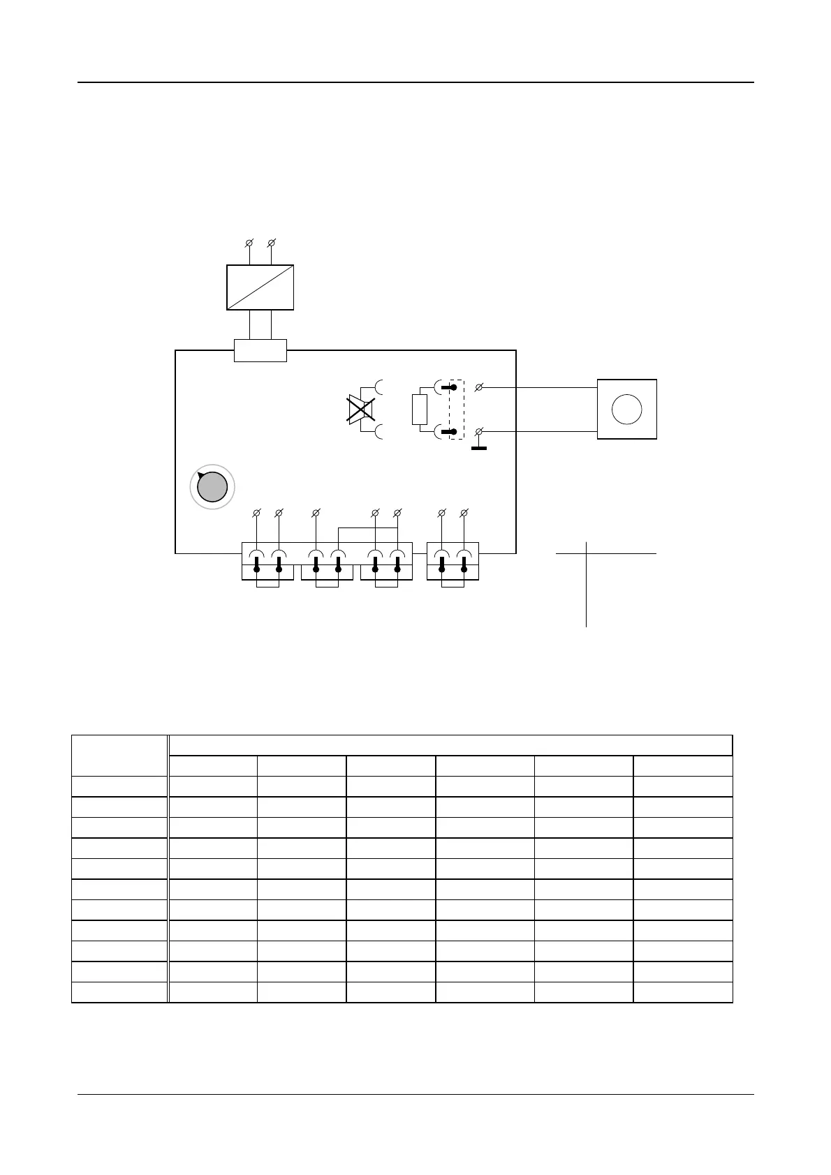 Loading...