SERVICE MANUAL
LBB 3310/00, 3330/00 and 3331/00 page: 26 Date of issue:
4822 861 11006 July 1998
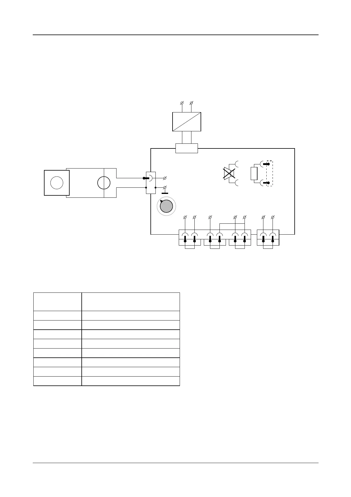
10.2.12 Functional test of the mode switch (S240)
Connect a current source of 0.5mA to the control-line CTRL-L1 via M4 Set the “mode switch” (S240) is each position
and measure the voltages at M4 related to M2 (GND)
X11
M2
M4
-
GND
4
+
0,5mA
CTRL-L1
I
Trunk
SHIELD
629548 27
25Ω
X205
X150X110
S240
X10
AC
24V DC
Power Supply
90 ... 264V AC
~~
Loudspeaker
PCB CPSU
M110 M111 M121 M122 M124 M150 M151
(GND) (GND) (GND)
+
-
A1
V
LR IN
Rec-INLine-IN Rec-IN Telephone
003_014.cdr
Figure 14
Mode switch
position (S240)
Measurement values for A1 (V)
Auto-1
9.5
Auto-2
5.8
Auto-3
4.5
Auto-4
3.9
Open-1
9.5
Open-2
5.8
Open-3
4.5
Open-4
3.9
 Loading...