SERVICE MANUAL
LBB 3310/00, 3330/00 and 3331/00 page: 19 Date of issue:
4822 861 11006 July 1998
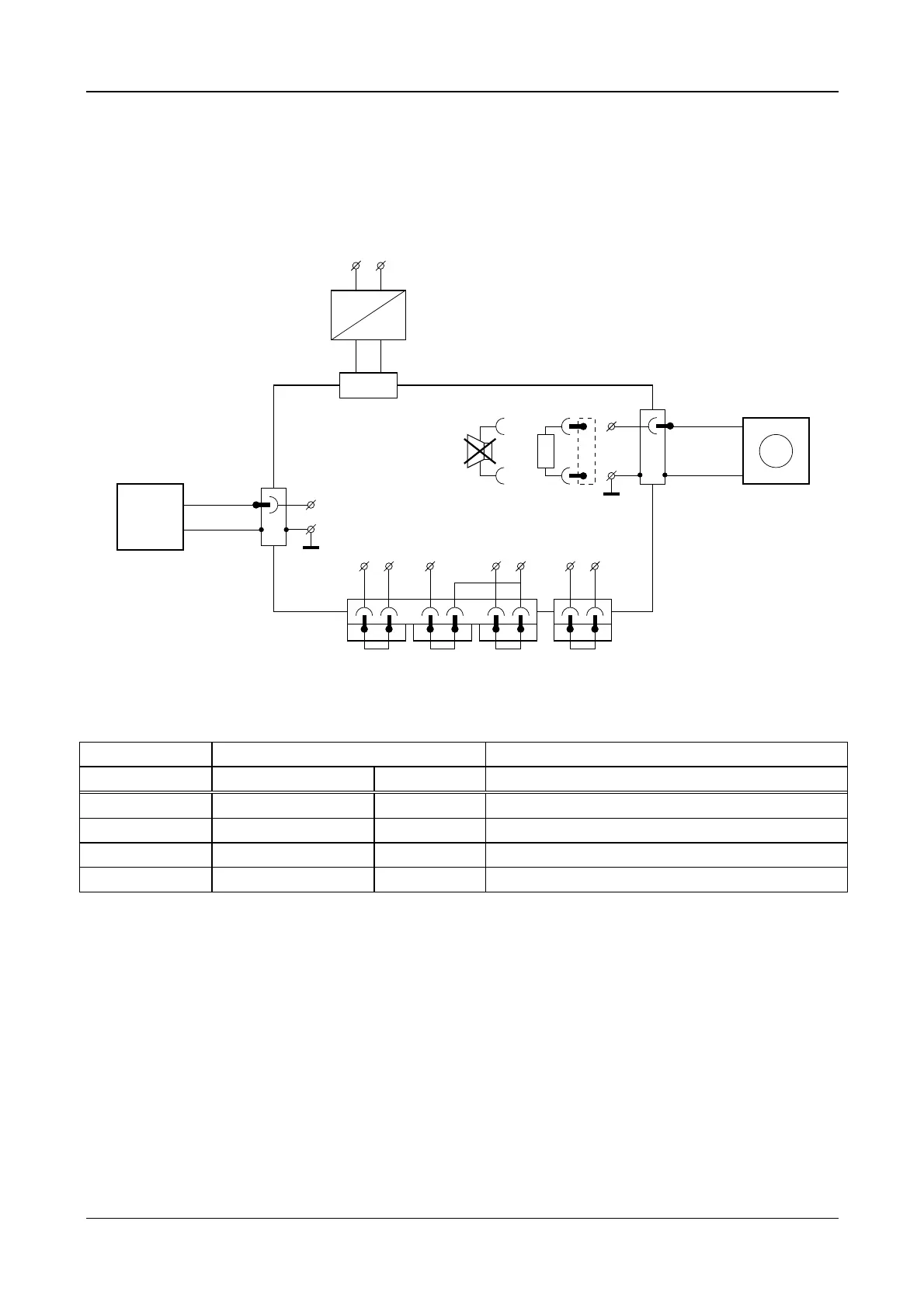
Nominal level, maximum level and bandwidth
Connect a sine-wave generator to one Trunk connectors (X11) and measure the output signal at the other Trunk
connector (X12) according to figure 7.
629548 27
25Ω
X205
X150X110
X10
AC
24V DC
Power Supply
90 ... 264V AC
~~
Loudspeaker
PCB CPSU
M110 M111 M121 M122 M124 M150 M151
(GND) (GND) (GND)
X11
M2
M1
GND
1Audio Contr.
Trunk
SHIELD
LR IN
Rec-INLine-IN Rec-IN Telephone
X12
Trunk
+
-
A1
V
GND
3
M2
M3
G1
Sine-Wave
Generator
+
-
003_007.cdr
Figure 7
settings for G1 measurement results for A1
Amplitude Frequency Amplification
Nominal level -36dBV (15.8 mVrms) 1kHz -9.4dBV +/- 1dB (85dB SPL)
Overload level -11dBV (281.8 mVrms) 1 kHz +3dBV +/- 1dB (115dB SPL)
Bandwidth -36dBV (15.8mVrms) 125 Hz -2dB +/- 2dB related to nom. level at 1kHz
Bandwidth -36dBV (15.8mVrms) 12.5 kHz -1dB +/- 1dB related to nom. level at 1kHz.
 Loading...