Faultfinding Guide
GB 57CDR779 8.
Figure 8-5 ‘Key matrix scan line’
Easy jog knob
Rotary operation
The easy jog knob (1050) incorporates a whole heap of user
control possibilities in just one knob. Without the knob being
operated, pin 1 and 3 of the knob (and thus pin 16 and 17 of
the display controller), maintain the +5V level. Turning the
knob clockwise briefly connects pin 1 to GND followed by pin
3.
Figure 8-6 ‘Turn clockwise’
Turning the knob anti-clockwise briefly connects pin 3 to
GND followed by pin 1.
Figure 8-7 ‘Turn anti-clockwise’
The pulses created this way arrive at pin 16 and 17 of the
display controller. The first pulse to arrive tells the controller
the direction of the rotation. Counting the pulses reveals the
amount of rotation. Combining and decoding this information,
the display controller will execute the appropriate task.
Push button operation
This button connects to the key matrix lines and thus the
operation is identical to the ordinary keys. Without being
pressed, pin 4 of the easy jog maintains the low level, pin 5
the high level. When pressed the scanning signal goes
through the closed contact of pins 4 and 5, and can be
checked at both pins.
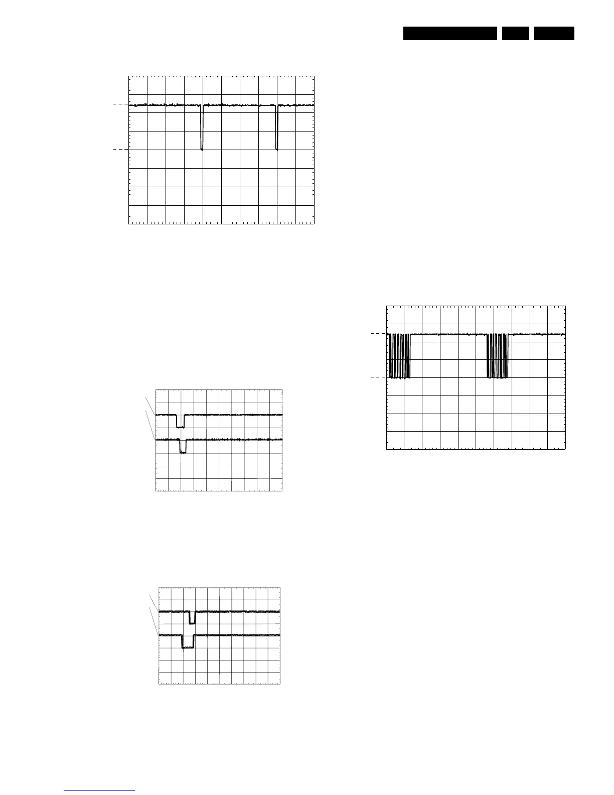
IR receiver - remote control
In the CDR570/930 the IR receiver TSOP1736 (6101) is
mounted on the display board. In the CDR770 that same IR
receiver (6200) is mounted on a small board together with the
headphone socket. In the CDR779 the IR receiver (6200) is
mounted on its own small board. In all versions the IR
receiver connects to the display controller. The signal coming
from the receiver can be checked at pin 22 of the display
controller. This signal is normally high (+5V). When the
remote control is being operated, pulses mixed in with the
+5V can be measured. The oscillogram gives an indication of
how the signal looks like with the RC being operated.
Figure 8-8 ‘IR receiver signal’
PM3392A
CH1!2.00 V= MTB5.00ms ch1+
0V
+5V
CL 96532076_026.eps
301100
PM3392
Pin3
Pin1
CH1 5.00 V=
CH2 5.00 V= MTB20.0ms- 1.92dv ch2-
CL 96532076_023.eps
301100
PM3392
Pin3
Pin1
CH1 5.00 V=
CH2 5.00 V= MTB20.0ms- 1.92dv ch2-
CL 96532076_022.eps
301100
PM3392A
CH1!2.00 V= MTB20.0ms ch1+
1
+5V
0V
CL 96532076_021.eps
301100