8 EN
Connect wires
Note
• Make sure that all loose leads are insulated with
electrical tape.
• Consult a professional to connect wires as instructed
below.
• Before connection, check the car's wiring carefully.
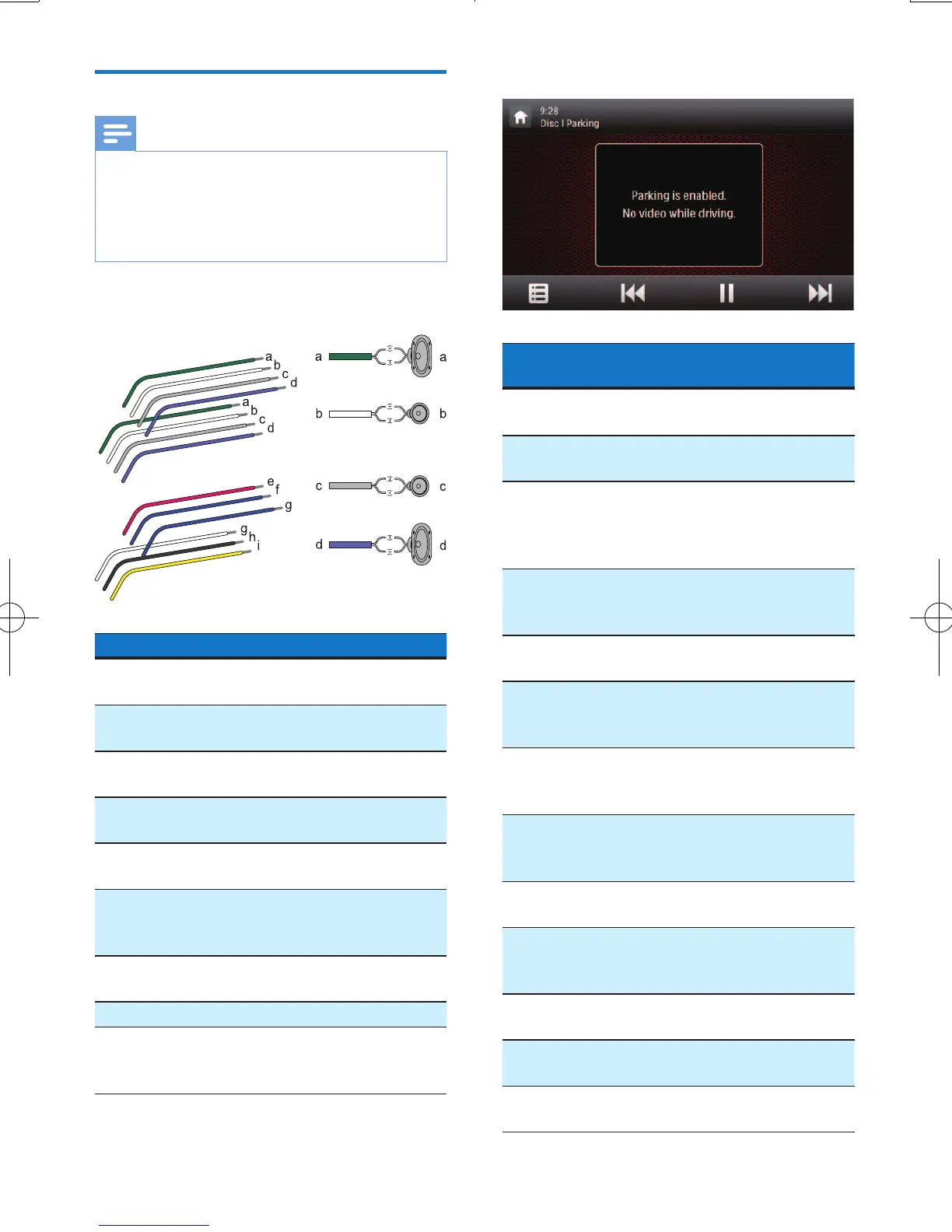
1 Connect the ISO male connectors.
ISO male connectors Connect to
a Green strip, black-
edged green strip
Rear left speaker
b
White strip, black-
edged white strip
Front left speaker
c Gray strip, black-
edged gray strip
Front right speaker
d
Purple strip, black-
edged purple strip
Rear right speaker
e Red strip Ignition key +12V
DC when ON/ACC
f Blue strip Motor/electric
antenna relay
control lead
g Blue strip, white strip Amplier relay
control lead
h Black strip Ground
i Yellow strip The +12V car
battery which is
energized at all times
2 Connect other wires if necessary.
Connectors and
sockets on rear panel
External sockets or
connectors
1 For ISO male
connectors
As indicated
above
2 REAR OUT R (Red
socket)
Rear right speaker
3 AV-IN R(Red socket) Right audio
channel output
socket of an
external player
4 AV-IN L(White
socket)
Left audio channel
output socket of
an external player
5 REAR OUT L (White
socket)
Rear left speaker
6 VIDEO IN (Yellow
socket)
Video output
socket of an
external player
7 VIDEO OUT 1
(Yellow socket)
Video input socket
of an external
display device
8 VIDEO OUT 2
(Yellow socket)
Video input socket
of an external
display device
9 RADIO ANTENNA
(Green socket)
Radio antenna
10 CAMERA IN (Purple
socket)
Video output
socket of an
external camera
11 SUB-W OUT (Blue
socket)
Sub-woofer
12 REVERSE CAMERA
(Purple wire)
Reverse camera
(B+)
13 PARKING BRAKE
(Pink wire)
Parking brake (-)