Reference : SGP_AVS_SW_ATLAS-05-05 Classification : COMPANY RESTRICTED
Version : 0.17 Project : ATLAS_DSW
Status : Proposed Chapter : User Manual
Date : 2006-09-12
Section : Diagnostic Software (Leco+)
© Philips Electronics N.V. 2006 Philips Semiconductors Page 8 of 124
2 USER INTERFACE 1
The table below shows an overview of the user interfaces of the DSW. The table is based on 2
logical interface, interfaces as seen from user perspective. A logical interface can use one or 3
more physical interface components. 4
The DVD Recorder has only a single RS232 port (service port) available for diagnostic or 5
debugging purposes, implying that all interfaces using this port are mutually exclusive. 6
7
Logical
Interface
Description Physical interface components
Command line
interface
Used to send commands from the
Control PC or Service PC to the
DVD Recorder DS.
• Control PC or service PC,
running a program (e.g. Asterix,
Compair, HyperTerminal),
connected to service port of the
DVD Recorder
• Test pin
Scripts
interface
Used to execute End-user/Dealer
Test Script.
• Local-Keyboard
• Local-Display
8
In the next chapters the logical user interfaces are described in more detail including the exact 9
use of the physical interface components. To switch between interfaces, the DVD Recorder 10
needs to be switched off and on again. 11
2.1 NUCLEI NUMERATION 12
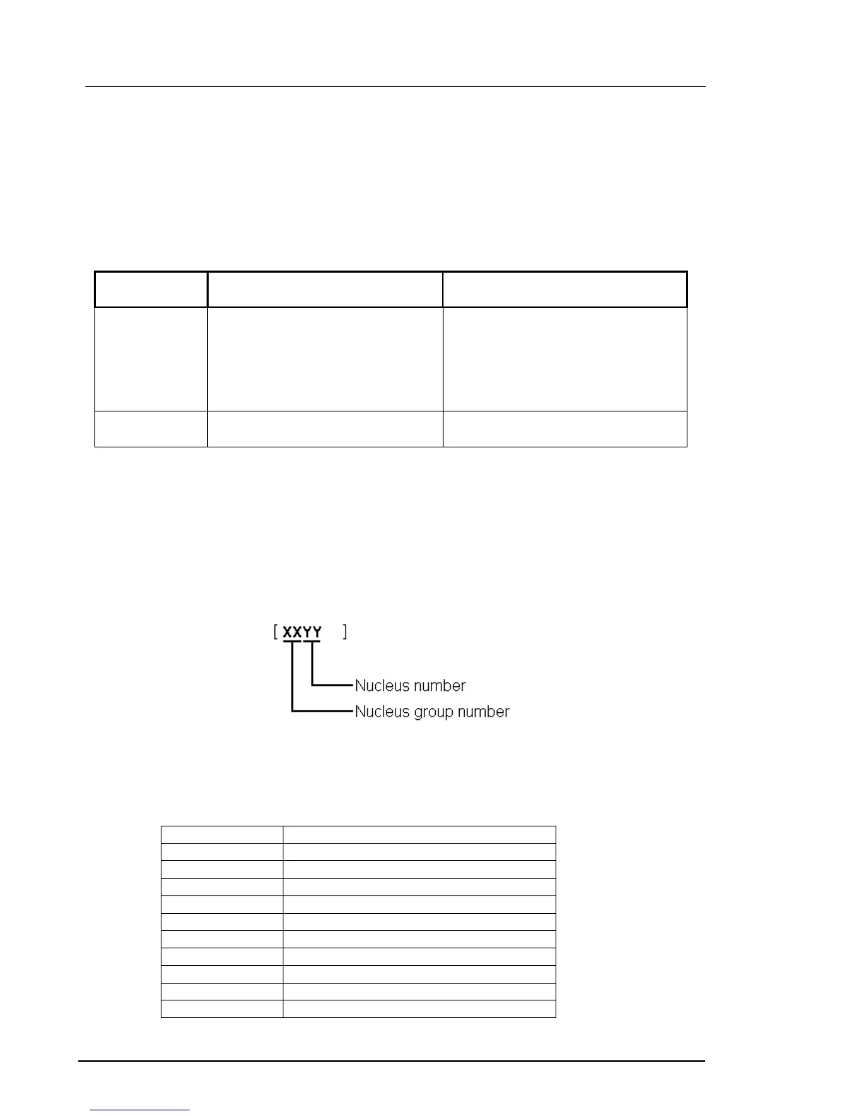
Each nucleus has a unique number of four digits. This number is the input of the command line 13
interface. 14
15
Figure 1 Unique number of a diagnostic nucleus. 16
The following groups are available for the LeCo+ DSW: 17
18
19
Group number Group name
0 Scripts
1 Codec (e.g. LeCo+)
2 Boot EEPROM
3 NVRAM (EEPROM of FLASH)
4 SDRAM (or DDR-RAM)
5 FLASH
6 Video Input Processor
7 DVIO
9 Basic Engine
12 System
 Loading...