Circuit Descriptions and List of Abbreviations
EN 104 FM249.
Start-up from Standby
When the monitor is in standby mode, it can wake-up in several
ways:
• When an RC command is received (RC_IN).
• Detection of H- and/or V-sync on VGA1.
• Detection of UART communication on VGA1.
• Detection of RS232 communication.
• Detection of Service modes.
RC Command Reception
When a RC command is received at the RC receiver on the
LED panel, it will go directly to the RC input of the OTC (RC_IN
on pin 100). If the monitor is in standby, and a proper RC
command is send, it will wake up.
The RC commands are routed to the Receiver box via the
VGA1 connector pin 9 (RC_VGA1), but this loop through
connection is controlled by RC_CNTL. Below is the truth table.
Table 9-5 RC Commands overview
Note: All RC commands are direct available on a separate RC-
out cinch connector (RC_OUT) on the VGA connector panel.
H- and/or V-sync Detection
When both H and or V sync are present on VGA1, there is a
pulse (low) on SYNC_ACT. When only H is present,
SYNC_ACT is continuously low. The SW disables the
interrupt, once an interrupt is received.
UART Communication Detection
When there is UART communication on VGA1, the UART
detection circuitry generates on every falling edge a pulse on
UART_ACT. This is a negative going pulse with a width of ±
470 s. The first pulse will trigger the main software to check for
the FTV System Protocol (FSP). The SW disables the interrupt,
once an interrupt is received.
RS232 Communication Detection
When an RS232 connection is made, and communication is
started (pulses on RS232_RXD), RS232_ACT becomes 'high'.
Via a transistor, RS232_ACT will make SERVICE_IN low.
When the Monitor is operating (+5 V available), this signal is
made low (in fact it is disabled).
Service Mode Detection
It is possible to enter four different Service Modes (provided the
OTC is still supplied by the +3V3_STBY).
Via the SERVICE_IN signal, which is an ADC input of the OTC,
a voltage drop is detected from +3.3 V to VX.
VX is a DC voltage, which represents the mode to be entered:
Table 9-6 Service Mode levels
I
2
C
There are four I
2
C busses used in the monitor (see also I
2
C
overview in chapter 6):
• I
2
C bus 1 is a (5 V) device bus, controlled by the OTC, and
connected to the following devices:
– PDP.
– EPLD.
– IO expander SCAVIO - PCF8574A.
– IO expander PSU - PCF8574A.
– ADC - PCF8591.
– Clock generator for PW - FS6377.
– Sound processor MSP3415G.
– Audio switch TEA6422 (Enhanced version only).
• I
2
C bus 2 is used for communication with the PixelWorks
co-processor (PW). Although the OTC is the main
controller, it will act in this case as a 'slave', since the PW
can only act as a 'master'. Before any I
2
C commands are
exchanged, the PW gets an interrupt (PW_START) to
indicate that the OTC wants to talk to the PW.
• I
2
C bus 3 is a (5 V) device bus, controlled by the PW, and
connected to the following devices:
– Video Decoder SAA7118 (Enhanced version only).
– De-interlacer SDA9400 (Enhanced version only).
– ADC/TMDS receiver AD9887.
– 3D Comb filter MN8783LSI (optional).
• I
2
C bus 4 is a (5 V) device bus, only connected to the NVM
(to avoid data corruption).
Notes:
• The PDP and EPLD are in fact 3.3 V bus devices, but they
need to be connected to bus 1, since the OTC is the first
controller to be fully operating at start-up. For this reason,
an I
2
C level shifter (items 7675/76 on diagram SC12) is
included, which converts the 5 V signals into 3V3 and visa
versa.
• One of the first commands is to set the clock generator
(item7570), else the PW can not start-up.
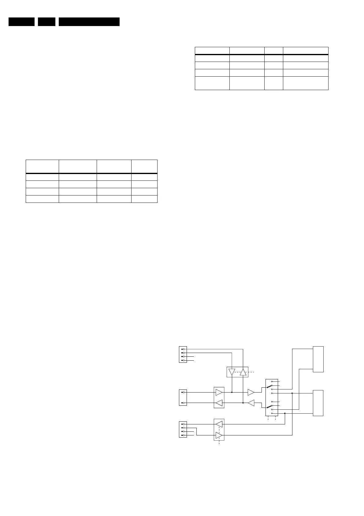
RS232/UART
Figure 9-17 RS232/UART
FTV2.1E-box FTV2.3Monitor RC
commands
RC_CNTL
In Standby In Standby Send to E-box Low
In Standby On Blocked High
On In Standby Send to E-box Low
On On Send to E-box Low
Service mode Limits Vx [V] Vx [V] Remarks
SDM 3.0 > Vx > 2.4 ± 2.6 0382-2 to GND
SAM 2.4 > Vx > 1.8 ± 2.0 0382-4 to GND
COMPAIR 1.8 > Vx > 1.2 ± 1.4 0382-6 to GND
RS232 active Vx < 0.8 >0.8 Plug in RS232, start
program
CL 26532038_013.eps
280302
ST232
74HC4052
RS232
9 pin Sub-D
3
TXD
RXD
VGA1_RXD
VGA1_TXD
TXD-OTC
RXD-OTC
TXD-PW
RXD-PW
VGA2_RXD
VGA2_TXD
2
74HCT
125-A/B
74HCT
125-C/D
VGA1
15 pin Sub-D
S1
S1..S4 = control signals
S1 = SELECT_1
S2 = SELECT_2
S3 = SELECT_3
S4 = SELECT_4
S4
4
11
12
15
VGA2
(FLEX VGA)
15 pin Sub-D
4
11
12
15
S3 S2
PW
OTC
n.c.
n.c.
n.c.
n.c.
www.freeservicemanuals.info
Digitized in Heiloo, Holland