Circuit Descriptions and List of Abbreviations
EN 103FM24 9.
9.4.4 Control (Diagrams SC7, 8 and 9)
Introduction
As a main controller, the so-called ARTISTIC is used, better
known as OTC (On screen display, Teletext and Control). It is
a 8051 (XA) based controller from Philips Semiconductors, the
SAA5801H.
Although the OTC is the main controller, it acts as a 'slave'
when communicating with the PixelWorks IC via the I
2
C-bus 2.
When the monitor is connected to an F21RE Receiver box, the
UART commands from the Receiver box will control the
monitor.
In stand-alone mode, the monitor can be controlled via the
Remote Control or via the RS232C port.
DDC1/2B (Display Data Channel, an I
2
C based protocol) is
implemented with separate NVMs for the two VGA inputs and
the DVI-D input as well.
It is also possible to use the RS232C port for software upload
to the PW Scaler and the OTC. The target for downloading is
controlled via a switch in the RS232C path; the switch itself is
controlled by the OTC.
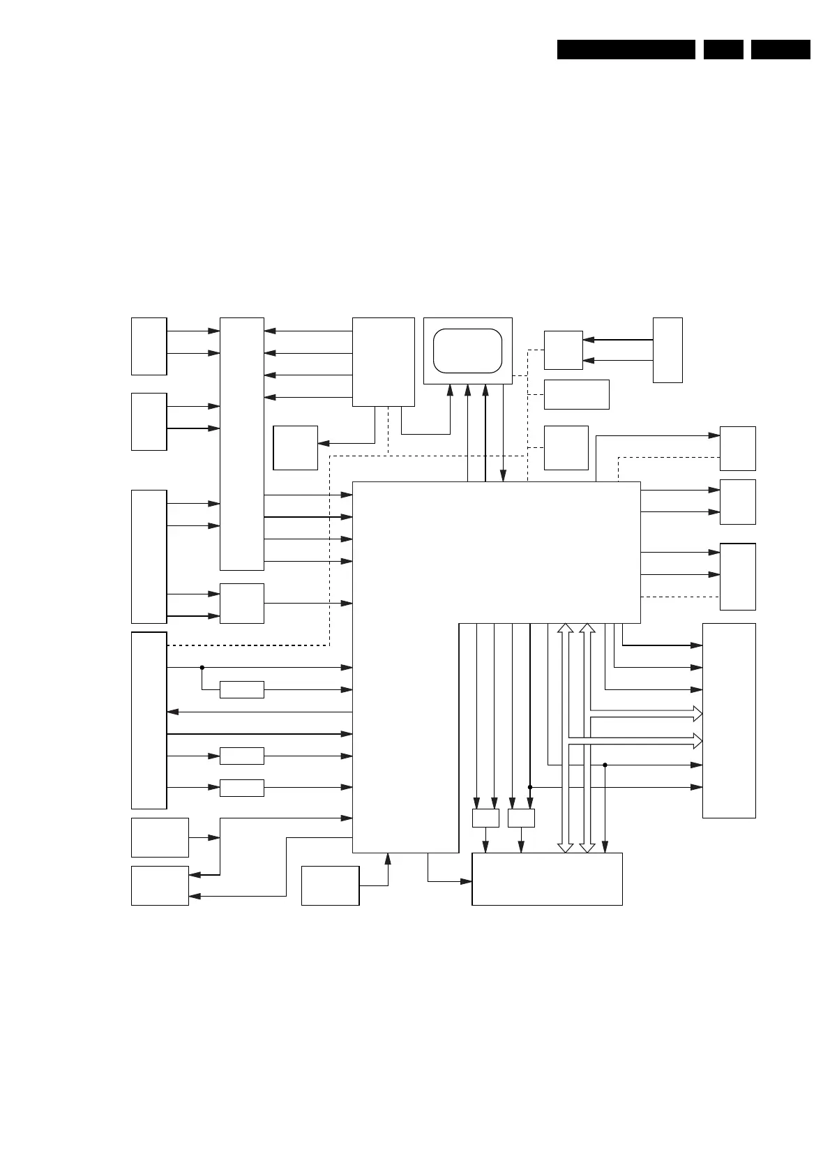
OTC Processor
Figure 9-16 Control Part
This part describes the Main Control part of the SCAVIO panel
and the interfaces with the software. The control function
consists of the following tasks:
• Control of external IOs, like fan speed, temperature,
service and RC5,
• UART communication with Receiver box,
• RS232 control / communication,
• Supports the uploading of new SW into the Flash-ROMs,
• Start-up of monitor and initialisation via I
2
C,
• Error detection and storing.
Start-up and Shut-down
The POR signal is not generated on the PSU, but on the
SCAVIO board. This is done with a fully integrated ADM810T
POR chip (item 7517), which senses the 3.3 V coming from the
PSU. The sense level is 3.08 V. During power-up as well as
power-down, this chip will make the RESET signal high. During
power-up, this signal will be held 'high' until 240 ms after V
CC
has become stable.
During power-down, the system will be reset as soon as the
V
CC
drops below 3.08 V.
CL16532099_004.eps
170801
RS232
IO
EXPANDER
PCF8574
PDP
TXD
7340 7540
7812
RXD
SELECT-1
SELECT-2
SELECT-3
SELECT-4
MSP-
RESET
POWER
DOWN
TEMP-1
TEMP-2
VGA2
(FLEX)
UART
RS232
SWITCH
SYNC
DETECT
&
RESET
AUDIO
(MSP)
7656
7530
EPLD
ADC
CLOCK
GENERATOR
CLOCK
GENERATOR
8V TEST
5V TEST
VGA2-TXD
VGA2-RXD
VGA1
PSU
VGA1-TXD
VGA1-RXD
VGA1-H
VGA1-V
8V
5V
RC5-IN
RC-CNTL
WP
7506
7510
8V-TEST
RS-232-ACT
SAA5801
OTC
PDP-GO
CPU-GO
IRQ-PDP
7383
I2C-1
UART-ACT
TXD-OTC
RXD-OTC
SYNC-ACT
I2C-1
5V-TEST
RAS
7500
7605
7430
PW-RESET
PW-START
I2C-2
RED-LED
NVM-WE
GREEN-LED
&
CASH
AC(0:9)
AC(0:20)
DC(0:15)
DC(0:15)
ROM-CS
RAM-CS
ROM-OE
RAM-OE
WE
CASL
POWER-OK
STANDBY
RESET
RC
RECEIVER
SERVICE
INPUT
DRAM
PW
LEDS
NVM
OTC
FLASH ROM
SERVICE_IN
RC-OUT
3V3-STBY
I2C-NVM
www.freeservicemanuals.info
Digitized in Heiloo, Holland