Circuit Descriptions and List of Abbreviations
EN 91FM24 9.
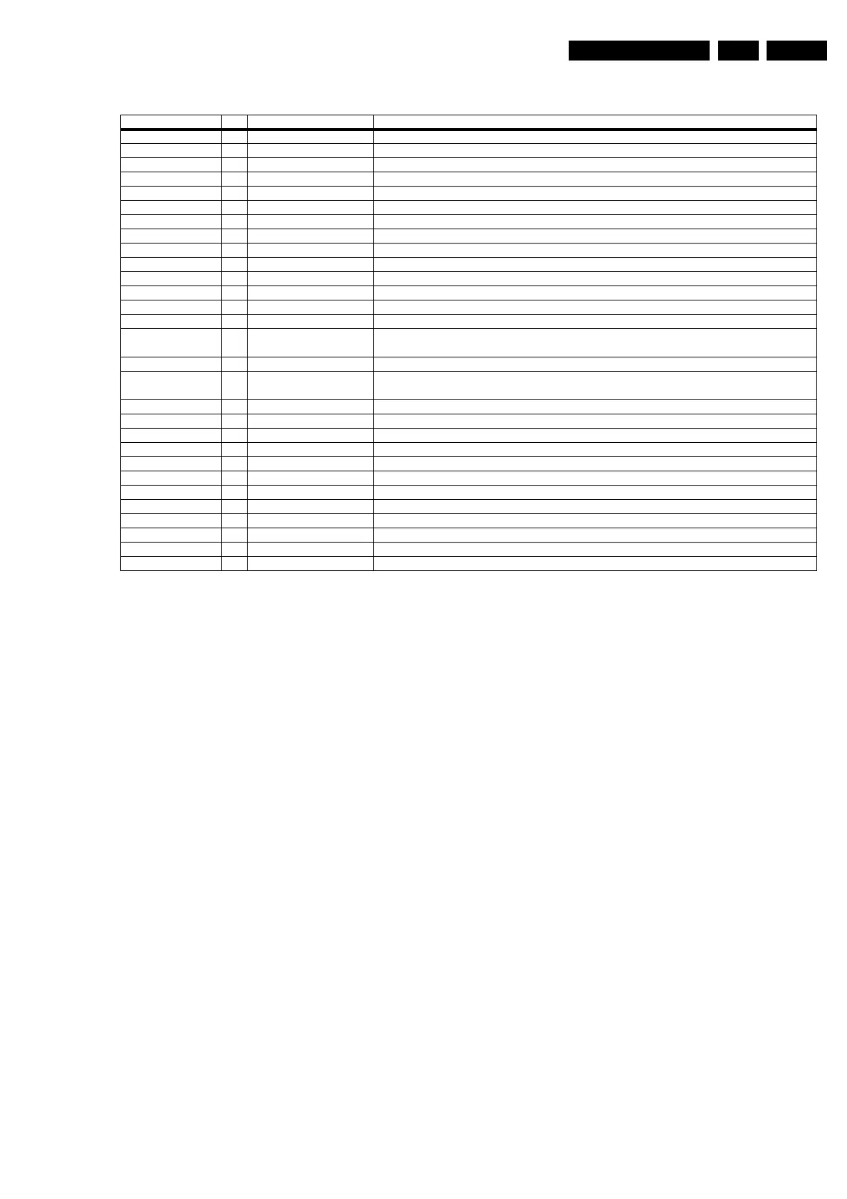
Table 9-1 I/O Overview Power Supply
The Power Supply Unit (PSU) is designed to provide regulated
output voltages for the plasma display panel (PDP) and the
built-in electronic panels (such as e.g. the SCAVIO and Audio
Amplifier panels).
It will house the Pre-conditioner, DC/DC converters and the
Standby circuitry. In addition, this panel will house the
protection and the (optional) fan drive circuitry.
The Mains inlet is mounted alongside the SCAVIO panel. It
consists of the necessary high and low frequency mains filters.
The mains AC voltage is applied to the input filter and then fed
to the standby supply. This supply is always operational and
delivers the +9V
STBY
voltage.
The task of the main supply is to deliver the supply voltages for
the several electrical circuits in the monitor.
It is switched via two single-pole relays, which are powered
from the +9V
STBY
voltage and controlled via the SUPPLY_ON
signal.
The reason to choose for a separate standby supply instead of
a single flyback supply is the requirement to have a low standby
power consumption.
The PSU consists of the following parts (which are described
separately):
• Mains inlet and filter,
• Standby supply,
• Fan control (optional),
• Pre-conditioner,
• LLC supply,
• Aux. supply,
• Protections.
To understand the descriptions below, see also mentioned
diagrams in Chapter 7.
9.2.2 Mains Inlet and Filter (Diagram P2)
Introduction
The mains filter provides common-mode and differential-mode
filtering, to fulfil legal and self-imposed limits. Additional
provisions are mains spikes and lightning protection.
Operation
The mains voltage is provided via mains inlet 0308, after which
it is fused by a T6.3A fuse (item 1400).
The next part, the mains filter, is optional. It consists of an LC
common mode filter section. This filter consists of two
capacitors (items 2402 and 2403) from both phase and neutral
to ground (to reduce the leakage current) and an inductor
(5401). Interferences on one of the phases are shorted to
ground via these capacitors.
Inductor 5401 also provides a differential-mode filtering with
capacitor 2400. Resistor 3401 discharges this capacitor after
the mains is disconnected.
A second common mode filter is made around coil 5402 and
capacitor 2401.
Resistor 3400 is a high energy VDR. The advantage of this
VDR is that it can handle 400 V
AC
without risk of fire. At high
voltage peaks (e.g. lightning surge) on one of the phases, the
resistance of VDR 3400 will be very low, causing fuse 1400 to
interrupt.
At a lightning surge on both phases with respect to chassis
ground, mains filter 5401 will form a high resistance, through
which the voltage will rise very sharply.
To prevent flashovers, a spark-gap/ resistor combination (items
1402 and 3404) is implemented.
The high-ohmic resistors 3402 and 3403 are connected
between neutral and chassis ground. They are required by
safety regulations.
Name I/O Value Description
+3V3 Out +3.3 Vdc To supply small signal digital circuitry.
+3V3_STBY_SW Out +3.3 Vdc To supply small signal digital circuitry, needing power in standby
+5V Out +5 Vdc To supply small signal digital circuitry.
+5V_STBY_SW Out +5 Vdc To supply small signal digital circuitry, needing power in standby
+8V6 Out +8.6 Vdc To supply the small signal analogue circuitry.
+9V_STBY Out +9 Vdc Signal to functional ON/OFF switch.
+9V_STBY_SW Out +9 Vdc Signal from functional ON/OFF switch.
DC_PROT In H/L Signal from audio amplifier to switch OFF the power supply in case of a safety problem.
FAN_SP_1 In H/L (TTL level) PWM signal from uP to control optional fans (group 1).
FAN_SP_2 In H/L (TTL level) PWM signal from uP to control optional fans (group 2).
FAN_SUPPLY_1 Out 5 to 13 Vdc Supply voltage for optional fans (group 1).
FAN_SUPPLY_2 Out 5 to 13 Vdc Supply voltage for optional fans (group 2).
Iak Out Signal to measure 'Ia' in PDP (Iak= 1 x Ia).
Mains In 110/240 Vac, 50/60 Hz Mains voltage.
POWER_OK Out H/L (TTL level) Signal to an interrupt pin of the uP, which indicates that the power supply is in regulation.
If an error occurs, signal goes from H to L.
SCL_1 In H/L I2C clock line from uP.
SDA_1 In/
Out
H/L Bi-directional I2C data line from/to uP.
STANDBY In H/L (TTL level) Signal to switch the PSU to standby mode.
Va Out +30 to +70 Vdc To supply the addressing circuitry in the PDP.
Vak Out Signal to measure Va in PDP (Vsk= 0.036 x Va).
Vcc Out +5 Vdc To supply small signal digital circuitry in the PDP.
Vcego In H/L (H= +2 Vdc) Signal to switch the low voltage supplies ON/OFF.
Vra In Signal to control Va (Va= 30 + (20 x Vra)).
Vrs In Signal to control Vs (Vs= 70 + (10 x Vrs)).
Vs Out +70 to +90 Vdc To supply the sustain circuitry in the PDP.
Vsago In H/L (H= +2 Vdc) Signal to switch the high voltage supplies (Vs and Va) ON/OFF.
Vsk Out Signal to measure Vs in PDP (Vsk= 0.029 x Vs).
VSND_POS Out +14.5 Vdc To supply the audio amplifier panel.
VSND_NEG Out -14.5 Vdc To supply the audio amplifier panel.
www.freeservicemanuals.info
Digitized in Heiloo, Holland