Circuit Descriptions and List of Abbreviations
EN 95FM24 9.
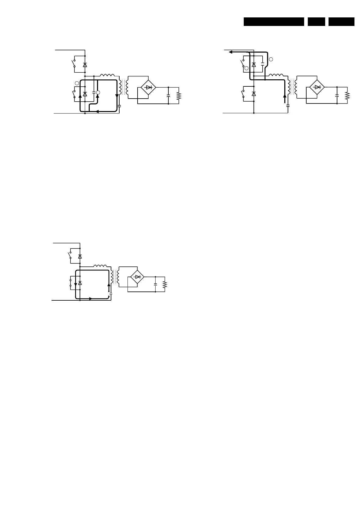
Phase 2 (S1 open, S2 open = dead time)
Figure 9-8 Phase 2 Resonance Supply
Before the current reaches zero, S1 is opened. Now, both
MOSFETs are not conducting. However, the current through
the coils wants to continue. The capacity Cp releases its load
to the series circuit, and the voltage at Cr continues to rise (Cp
is the sum of several parasitic capacities).
1) The voltage at the drain of MOSFET 2 drops, because Cp is
discharged at this moment [1]. This causes a voltage inversion
across Lr and Lp. The secondary winding begins to feed back,
charging capacitor Cs.
2) The voltage becomes negative, and diode D2 starts to
conduct [2]. The secondary bridge remains conducting.
Phase 3 (S1 open, S2 closed)
Figure 9-9 Phase 3 Resonance Supply
The gate of MOSFET 2 is becoming high. The current through
D2 is taken over by MOSFET 2. The switching losses are
negligible, because the voltage across the switch is now
approximately 1 V.
The current through Lr starts negative, but is increasing to
change polarity. A current flows through MOSFET 2 and the
series circuit. The bridge remains conducting, but its current
gets zero because of the decreasing voltage across Lp. This is
caused by the discharge of capacitor Cr. The voltage at
capacitor Cr is decreasing sinusoidal and so is the voltage
across Lp and Lr.
Phase 4 (S1 open, S2 open = dead time)
Figure 9-10 Phase 4 Resonance Supply
Before the current reaches zero, S2 is opened. Now, both
MOSFETs are not conducting, but the current through the coils
wants to continue. The capacity Cp releases its load to the
series circuit, and the voltage at Cr continues to fall (Cp is the
sum of several parasitic capacities).
1) The voltage at the drain of MOSFET 2 increases, because
Cp is discharged at this moment [1] (Cp was charged to 400 V).
This causes a voltage inversion across Lr and Lp. The
secondary winding begins to feed back, charging capacitor Cs.
2) The voltage becomes higher than 400 V, and diode D1 starts
to conduct [2]. The secondary bridge remains conducting.
Protections MC34067
Over Current Protection (OCP)
The voltage at R3021 is a criterion for the current, which flows
through the primary winding. Via C2015 and D6010, the
negative information is clamped at -0.6 V. The total amplitude
is rectified via D6009 and C2010, and via R3020 and TS7009
supplied to the fault input (pin 10) of the controller.
When the fault input is higher than 1 V, the protection is
activated.
Over Voltage Protection (OVP)
The voltage at R3010 is the take-over-winding voltage. This
voltage is also supplied to pin 10 of the controller via a voltage
divider R3010/R3011 When the fault input is higher than 1 V,
the protection is activated.
Soft-start Over Current Protection
If short-term ‘over current peaks’ occur, the frequency is
adapted. The voltage at R3021 is clamped at -0.6 V via C2015
and D6010. The total amplitude is rectified via D6011 and
C2008, and supplied to the 'capacitive' thyristor TS7017/18 via
R3012.
When the voltage at the emitter of TS7017 gets higher than 5
V, the soft-start capacitor C2027 is discharged and the
frequency increases. Because of this, the V
S
will drop. If this
voltage remains 5 V, the supply is interrupted (hick-up).
This circuit is adjusted in such a way, that the voltage does not
drop too much if a flash occurs.
Lr
S1
S2
Vi
+
Br1
D1
Cp
CL 96532069_168.eps
300999
D2
Lp
Cr
Cs
1
2
Lr
S1
S2
Vi
+
Br1
D1
CL 96532069_169.eps
300999
D2
Lp
Cr
Cs
CL 96532069_170.eps
300999
Lr
Lp
Cr
S1
S2
Vi
+
Br1
D1
Cp
D2 Cs
1
2
www.freeservicemanuals.info
Digitized in Heiloo, Holland