Do you have a question about the Philips FW-C100/21 and is the answer not in the manual?
Details features and board usage across different system versions.
Covers mains, amp, tuner performance parameters.
Specifies tape drive performance and CD playback characteristics.
Describes test configurations for audio components.
Lists required tools and electrostatic discharge protection gear.
General warnings about electrostatic discharge sensitivity.
Warning about invisible laser radiation when open.
Critical safety instructions before operating the player.
Information on packaging and disposal of materials.
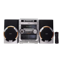
List of items included with the system.
Connecting speakers, antennas, and external equipment.
Connecting the AC power cord to the system and outlet.
Instructions for inserting batteries into the remote control.
Explains the function of all buttons on the unit and remote.
Adjusting display brightness levels.
Turning the system on/off and choosing audio input sources.
Volume, DSC, and DBB function descriptions.
Operations related to CD loading and playback.
Playing tracks in random or repeating order.
Manually tuning and saving radio stations.
Selecting stored radio stations.
Adjusting tuning frequency steps.
Inserting, playing, rewinding, and fast-forwarding tapes.
Recording from various sources, synchro start, and dubbing.
Connecting and selecting external audio sources like TV or VCR.
Displaying and setting the system's clock.
Setting the system to turn on/off automatically or after a delay.
Resolving CD playback errors and general system non-responsiveness.
Troubleshooting poor radio signals and tape recording/playback faults.
Addressing sound problems and non-functional remote controls.
Instructions for removing the cassette cover and opening the CDC tray.
Procedures for removing the front panel assembly.
Removing front and rear assemblies and boards.
Illustrates service positions for disassembly and repair access.
Procedures for testing tuner, CD, and EEPROM functionalities.
Visual representation of the system's functional blocks and signal flow.
Visual representation of electrical connections between system components.
Pin assignments for the front display unit.
Lists component variations for the front board by model number.
Diagram showing the functional blocks of the ECO5 tuner board.
Alignment procedures and values for the ECO5 tuner.
Diagram illustrating the structure of the Tuner 95 board.
Alignment procedures and values for the Tuner 95 board.
Diagram showing the functional blocks of the ECO MTF module.
Detailed list of electrical components for the ECO MTF module.
Critical warnings for replacing the CD mechanism and ESD protection.
Visual guide to wiring connections within the CD mechanism.
Diagram illustrating CD mechanism, servo, and laser control functions.
Shows component placement on the main board (copperside).
Detailed schematic for the CD drive and servo control circuits.
Exploded view and parts list for the 3CDC-LC module.
Comprehensive list of resistors and diodes used in the module.
Block diagram for the 3CDC-LC-MB module.
Component placement on the MB module's copperside and componentside.
Detailed schematic for the MB module circuits.
List of electrical components for the MB module.
Overview of the Combi board's functions and sections.
Sections detailing karaoke and headphone output circuits.
Comprehensive list of electrical components for the Combi board.
| Brand | Philips |
|---|---|
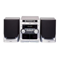
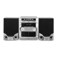
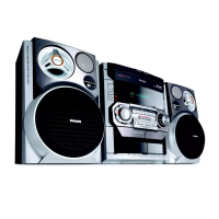
| Model | FW-C100/21 |
| Category | Stereo System |
| Language | English |