Do you have a question about the Philips HTD3510/12 and is the answer not in the manual?
| Brand | Philips |
|---|---|
| Model | HTD3510/12 |
| Category | DVD Player |
| Language | English |
Details about the amplifier's output power, frequency response, and signal-to-noise ratio.
Lists video formats, HDMI resolutions, audio inputs, and FM radio tuning ranges.
Details USB compatibility and supported media/file formats.
Explains regional code support for DVDs based on country.
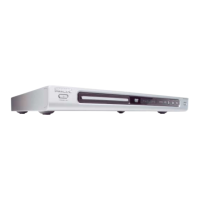
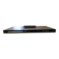
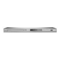
Details power supply, consumption, physical dimensions, and weight for the main unit.
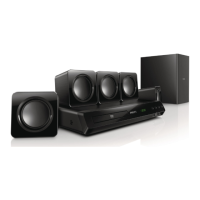
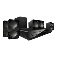
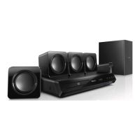
Provides specifications for subwoofer and speakers, including power, dimensions, and weight.
Describes the laser type, wavelength, output power, and beam divergence.
Guidelines for safe repair, including isolation transformers and component replacement.
Warnings and instructions regarding laser safety and handling during servicing.
Precautions against electrostatic discharge (ESD) and handling live voltage sections.
Guidelines for lead-free soldering, using original spare parts, and handling BGAs.
Multilingual instructions for reading safety information before product use.
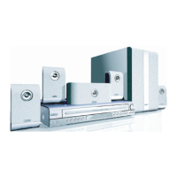
Visual guide for connecting the home theater system and to the TV.
Steps for powering on, initial setup, and using the home theater system.
Step-by-step guide on how to dismantle the player for servicing.
Instructions for upgrading software via USB or disc, including version verification.
Flowchart for diagnosing and resolving no audio output problems.
Flowchart for diagnosing VFD/LED display and button issues.
Flowchart for diagnosing and fixing remote control problems.
Flowchart for diagnosing issues with disc reading or door operation.
Illustrates internal connections and functional blocks of the main and amplifier boards.
Detailed schematic of the front control board's circuitry.
Detailed schematic of the power board's circuitry.
Schematics for main board power, SPHE8203R, video, audio, HDMI, USB, and amplifier circuits.
Top-side view of the front control board's component placement.
Top-side view of the power board's component placement.
Top and bottom views of the main board's component placement.
Pin assignments and voltages for the XS751 connector.
Pin assignments and voltages for XP221 and XP82 connectors.
Pin assignments and signals for XP135, XP136, and XP100 connectors to the loader.
Illustrates internal functional blocks and interfaces of the SPHE8203R main IC.
Detailed description of each pin function for the SPHE8203R IC.
Shows a breakdown of the unit's components and their assembly.
Shows a breakdown of components and assembly for specific models.
Shows a breakdown of components and assembly for specific models.
Lists the versions and release dates of the service manual.