Mechanical Instructions
EN 15LC03E 4.
Continue with the paragraph 4.3.3.
4.3.2 For 23 inch model
Manually unlock and remove the IO connector cover cap.
Figure 4-5 TV rear cover removal 23” model
4.3.3 For all models
1. Make sure all power-, audio-, video-, coax-, and SCART
cables are unplugged.
2. Remove the five Torx screws securing the monitor rear
cover.
3. Carefully remove the rear cover and store it on a safe
place.
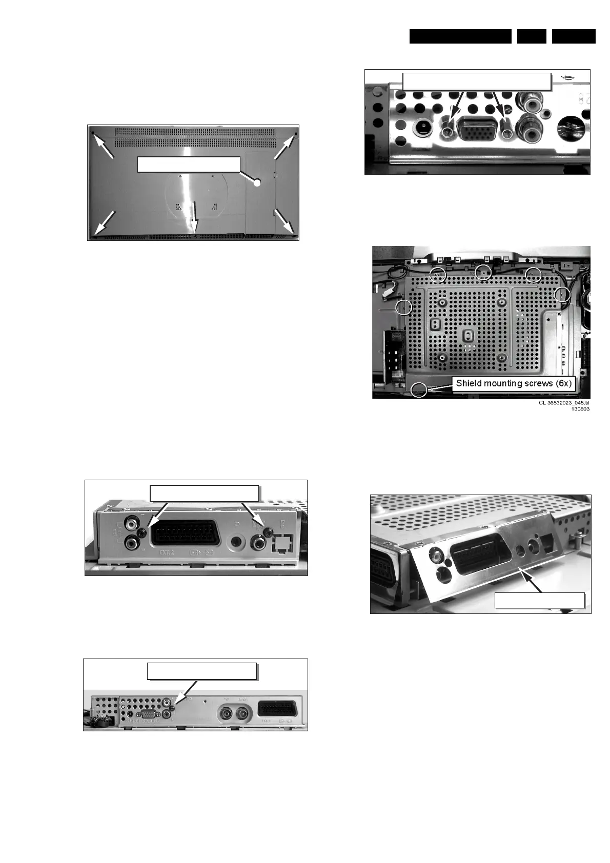
4.4 Shield Removal
• Remove at the “SCART plug side” the screw besides the
plug.
• Remove the connector plate.
Figure 4-6 TV SCART plug side
• Unscrew, at the bottom side, the connector plate screw and
remove this plate.
Figure 4-7 Bottom side connector plate
• Use a 5 mm socket screwdriver to remove both connector
distance bolts from the “PC input / VGA-in” socket.
Figure 4-8 VGA Connector screws
• Remove all shield mounting screws.
Figure 4-9 Shield with mounting screws
• Bend at the ”SCART-plug side” the thin metal electrostatic
shield away from the sockets, so the complete shield can
be lifted later on.
Figure 4-10 Shielding
• Unlock the shield by carefully moving it a few millimetres to
the bottom side of the monitor. The topside of the shield
has to detach from underneath the two lock clamps, which
secure the shield at topside. Carefully lift the shield with
respect for the cables and/or connector sockets. Take out
the shield and store it on a safe place.
CL 36532044_002.eps
160503
Connector cover cap
CL 36532044_003.eps
160503
Connector plate screws
CL 36532044_004.eps
160503
Connector plate screws
CL 36532044_006.eps
160503
VGA connector distance screws
CL 36532044_007.eps
160503
Electrostatic shield