Mechanical Instructions
EN 16 LC03E4.
4.5 I/O Removal
4.5.1 Side I/O assy removal for 15/17 inch model
Figure 4-11 Side I/O assy removal for 15”/17” model
1. Disconnect the cable connector [0240] from the side I/O
assy.
2. Unlock this unit by shifting it one centimetre to the outside
direction of the monitor.
3. Take out this side I/O assy.
4.5.2 Side I/O assy removal for 23 inch model
Figure 4-12 Side I/O assy removal for 23” model
1. Disconnect the cable connector [0240] from the side I/O
assy.
2. Unlock this unit by pushing it one centimetre in horizontal
direction (to bottom side) of the monitor.
3. Take out this side I/O assy.
4.6 Front LED Panel Removal
4.6.1 Only for the 23 inch model
To gain access to the Front LED panel unscrew and remove
the three mounting screws from the loudspeaker box covering
the panel. Release cables and take out the loudspeaker box.
Continue with the paragraph 4.6.2.
4.6.2 For all models
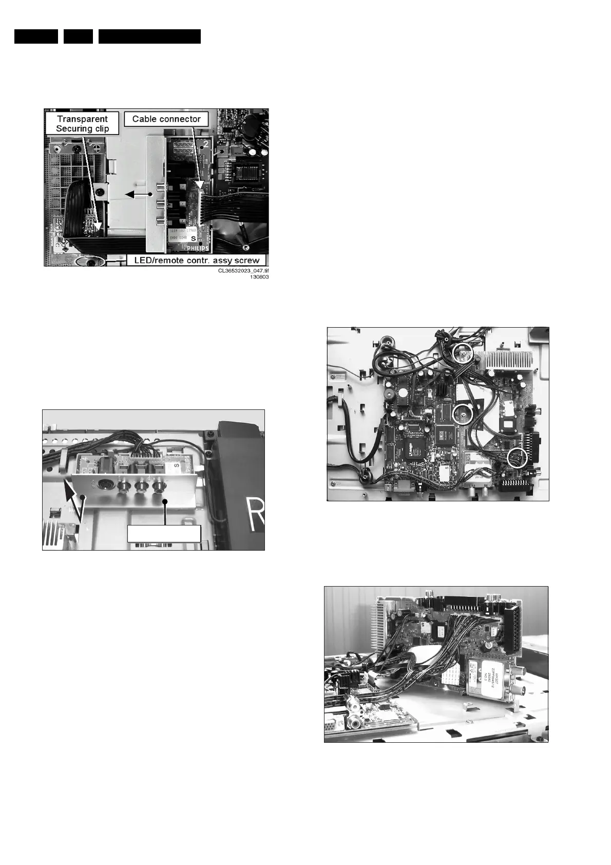
1. Unlock the transparent securing clip, which holds the Front
LED panel in place, and take out the Front LED panel .
(See previous figure: “Side IO assy removal for 15”/17”
model).
2. To completely remove the Front LED panel (incl. Lens),
remove the assy screw.
4.7 TV Board Removal
4.7.1 For 15 /17inch model
Disconnect all five TV board connectors out of the regarding
sockets [3225], [1234], [1231], [1902], and [1732].
Continue with the paragraph 4.7.3.
4.7.2 For 23 inch model
Disconnect all six TV board connectors out of the regarding
sockets [3225], [1233], [1231], [1902], [1732] and [1734].
Continue with the paragraph 4.7.3.
4.7.3 For all models
1. Pull the thin flat cable out of its special shaped connector,
[1010].
2. Unscrew and remove the three TV board mounting screws.
3. Take out the TV board.
Figure 4-13 TV board
Note: Sometimes it is necessary to place the TV board in its
service position, for easy signal measuring. See picture below.
Figure 4-14 TV board in service position
CL 36532044_008.eps
021003
Side I/O Assy
CL 36532044_012.eps
160503
CL 36532044_010.eps
160503
CL 36532044_010.eps
160503