Mechanical Instructions
EN 17LC03E 4.
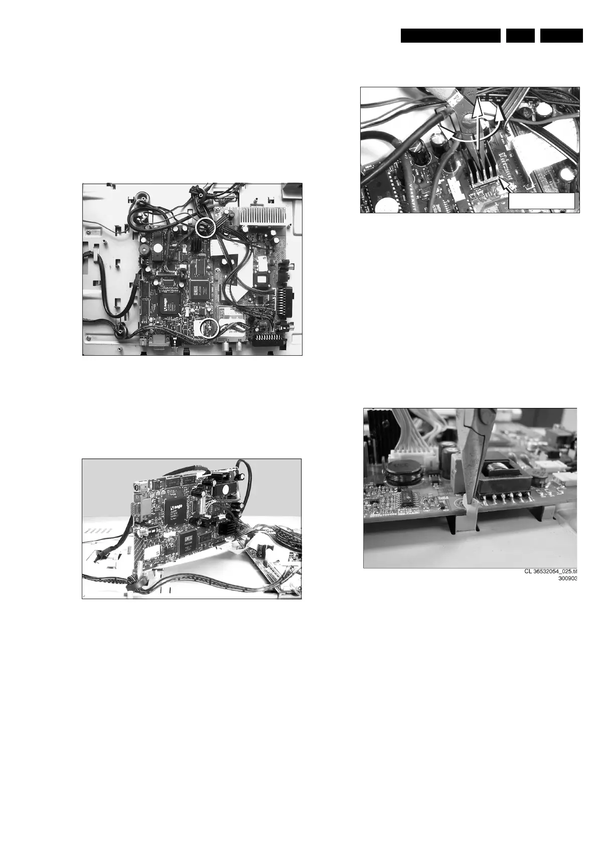
4.8 Scaler Board Removal
1. Carefully disconnect the cable connector in the centre of
the Scaler board [1506]. Take care not to damage the
fragile cables.
2. Disconnect the cable connectors at the edge of the Scaler
board [1402] and [1003].
3. Pull the thin flat cable out of its special shaped connector
[1681].
4. Unscrew and remove two Scaler board mounting screws.
5. Take out the Scaler board.
Figure 4-15 Scaler board
Note: Sometimes it is necessary to place the Scaler board in a
service position. In this case it is necessary to use the specific
“Repair kit scaler board” including two extra long cables (order
nr. 3122 785 90490).
Figure 4-16 Scaler board in service position
Important: Video converter chip heat sink.
1. Before you de-solder the video converter chip SAA7118
from the board, the heat sink must be removed from the
chip. Use a pair of pliers to remove the heat sink by means
of a twist- and pull movement (see figure). Store the heat
sink on a safe place, adhesive side up!
2. Place the self-adhesive heat sink back in place after the
chip exchange action has been finished.
Figure 4-17 Heat Sink Removal
4.9 Inverter Board Removal (only for 15/17 inch
model)
Note: The Inverter board is available in two versions: one
model for TN-displays and another model for IPS-displays. The
(dis)assembly procedure is the same for both versions.
1. Disconnect the cable from the Inverter board.
2. Disconnect at top and bottom side all the black/white and
pink cable connectors.
3. Use a pair of pliers to bend the metal securing clamp in
such a way that the Inverter board can be taken out.
4. Remove the Inverter board and store it on a safe place.
Figure 4-18 Inverter board
4.10 Top Control Assy Removal
1. Remove the cable from the Top control assy [1500].
2. Remove both mounting screws that secure the Top control
assy to the monitor frame.
3. Take out the Top control assy.
CL 36532044_013.eps
160503
CL 36532044_011.eps
160503
CL 36532044_014.eps
160503
1
2
Heat sink