2-2
2-2
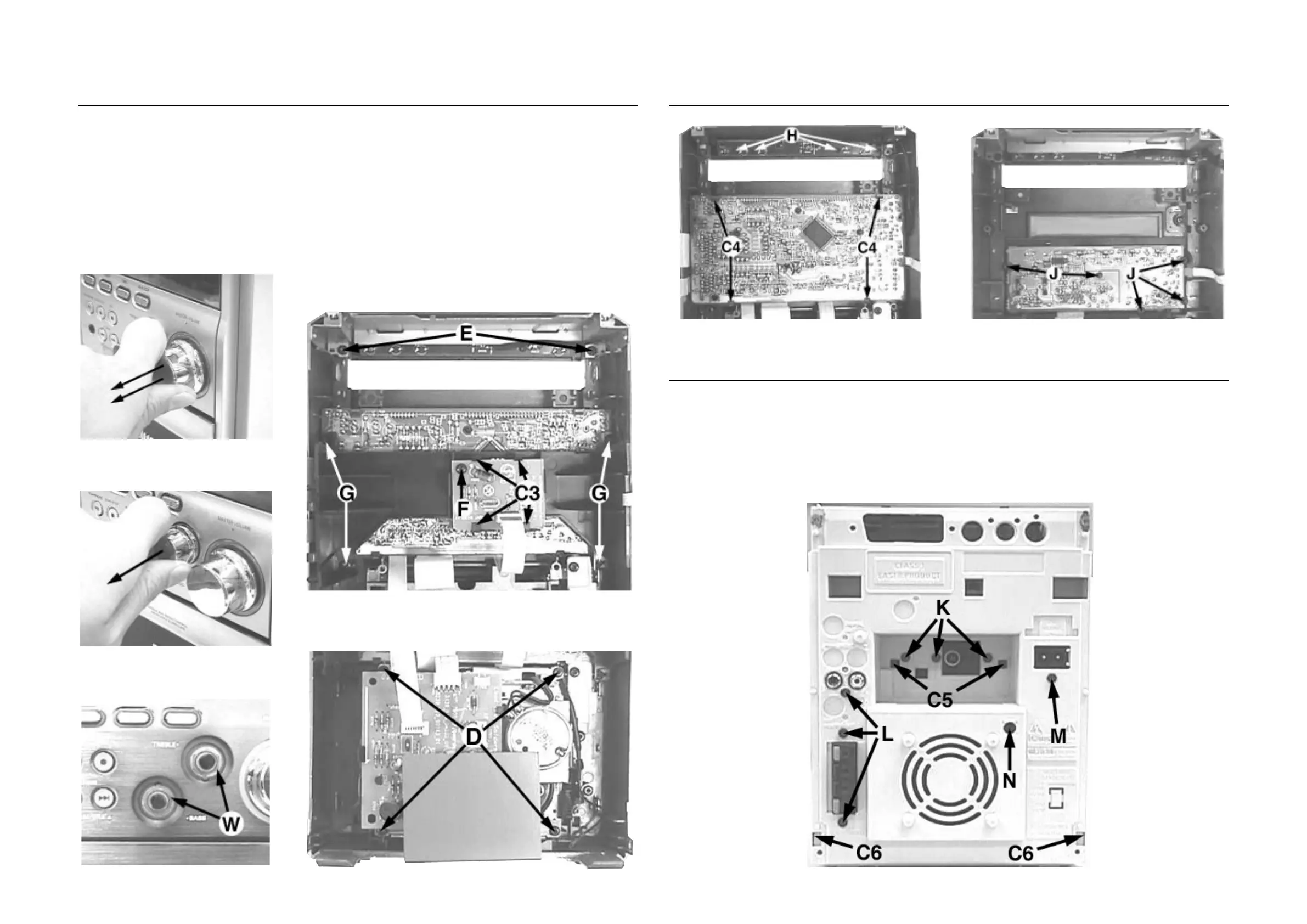
Dismantling of the Front Panel assembly
1) The Knob Volume (pos 141) can be remove by pulling it
out in the direction as shown in Figure 8.
2) The Knob Bass/Knob Treble (pos 140) can be remove by
pulling it out in the direction as shown in Figure 9.
3) Loosen 4 screws D (see Figure 12) to remove the Shield
Tape Deck and Module Tape Deck (pos 1107).
4) Loosen 2 screws E (see Figure 11) to remove the Bracket
Top Support (pos 113).
DISMANTLING INSTRUCTIONS
5) Loosen 1 screw F and 4 catches C3 (see Figure 11) to
remove the Eeprom Board (pos 1105D).
6) Loosen 4 screws G (see Figure 11) to remove the Bracket
Combi (pos 155).
7) Uncatch 4 catches C4 (see Figure 13) to remove the
Display Board (pos 1105A)
8) Loosen 4 screws H (see Figure 13) to remove the Top
Key Board (pos 1105C).
9) Loosen 5 screws J (see Figure 14) and 2 nuts W (see
Figure 10) to remove the Control Board (pos 1105B).
Dismantling of the Front Panel assembly
Figure 11
Figure 9
Figure 12 Figure 15
Figure 13
1) Loosen 3 screws K and 2 catches C5 (see Figure 15) to
remove the Tuner Board assembly.
2) Loosen 3 screws L (see Figure 15) to free the Combi
Board (pos 1102-1003).
3) Loosen 1 screw M (see Figure 15) to free the Mains
Socket Board (pos 1102-1001B).
4) Loosen 1 scew N and 2 catches C6 (see Figure 15) to
free the Panel Rear (pos 230) by sliding it out towards the
rear.
Note : Tuner Board assembly and Mains Socket Board
can also be remove together with the Panel Rear.
Dismantling of the Rear Panel assembly
Figure 14
Figure 8
Figure 10