2-2
2-2
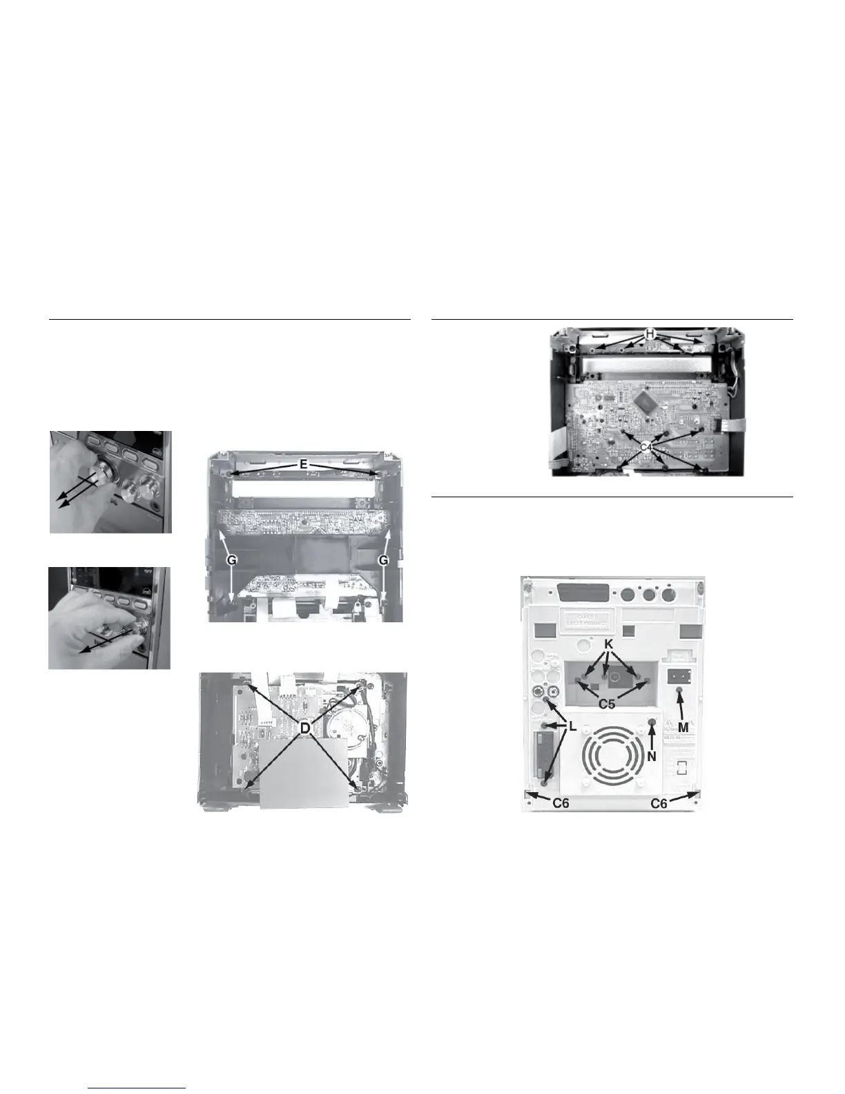
Dismantling of the Front Panel assembly
1) The Knob Volume (pos 10) can be remove by pulling it
out in the direction as shown in Figure 7
2) The Knob Bass/KnobTreble(pos 11) canbe removeby
pulling it out in the direction as shown in Figure 8.
3) Loosen 4 screws D (see Figure 10) toremove the Shield
Tape Deck and Module Tape Deck (pos 29).
4) Loosen2 screws E (seeFigure9)to remove theBracket
Top Support .
DISMANTLING INSTRUCTIONS
5) Loosen4screwsG(seeFigure9)toremovetheBracket
Main.
6) Loosen 6 screws C4 (see Figure 11) to remove the
Display Board.
7) Loosen 4 screws H (see Figure 11) to remove the Top
Key Board.
Dismantling of the Front Panel assembly
Figure 9
Figure 8
Figure 10 Figure 12
Figure 11
1) Loosen 3 screws K and 2 catches C5 (see Figure 12) to
remove the Tuner Board assembly.
2) Loosen 3 screws L (see Figure 12) to free the Main
Board.
3) Loosen 1 screw M (see Figure 12) to free the Mains
Socket Board.
4) Loosen 1 screw N and 2 catches C6 (see Figure 12) to
freethe Panel Rear(pos 53) byslidingit out towardsthe
rear.
Note : Tuner Board assembly and Mains Socket Board
canalsoberemovetogether with the Panel Rear.
Dismantling of the Rear Panel assembly
Figure 7