Alignments
EN 57SDI PDP 8.
8.3 Alignments 42” SD v3
1. Get Pattern to be Full White.
2. Adjust Vsch to 40 V with VR5004.
3. Check the waveform with an Oscilloscope.
• Triggering through V-sync of LOGIC Board.
• Connect the OUT 4 Test Point at the centre of Y_buffer
to other channel, and then check the first SF operating
waveform of 1TV-Field.
• Check the waveform as before by adjusting Horizontal
Division. Check the Reset waveform when the
V_TOGG Level is changed.
• Set the Vset to 10µs by adjusting VR5002.
• Set the Falling maintenance time to 30 µs by adjusting
R5003.
• Change the waveform position of Oscilloscope to 3SF
and then set the Falling maintenance time to 30µsby
adjusting the VR5001. GND maintenance section
should be checked after the Vertical Division is
readjusted to '2 V or 5 V'.
Special notice: When you adjust the inclination of waveform,
do check and adjustment being based on the Reset waveform
of 1st Sub-field of 1st Frame and then move to 3rd Sub-field for
adjusting.
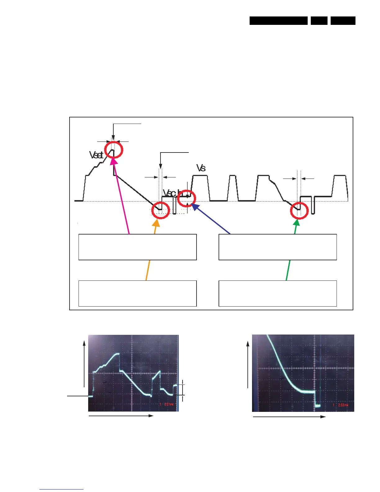
Figure 8-13 TCP ramp waveform inclination adjustment (Y-Board)
Figure 8-14 Rising ramp
Figure 8-15 Falling ramp
Adjust VR5003 to set the time of
Yfr (Falling Ramp_1st) 30
µs
Adjust VR5002 to set the time of
Yrr (Rising Ramp) 10
µs
Adjust VR5001 to set the time of
Yfr (Falling Ramp_3rd) 30
µs
Adjust VR5004 to set the voltage of
Vsch (Scan high voltage) 40 V
rising maintenance time
falling maintenance time
(V)
50V/div.
DC=0V
20ms/div.
(t)
40V
(V)
20V/div.
50ms/div.
(t)